The Thermal Challenge in SMT Power Modules
Modern SMT power modules — including DC-DC converters, motor drivers, and RF power amplifiers — face an increasingly acute thermal challenge. Power densities of 50-200 W/cm² at the semiconductor junction are now common, driven by the miniaturization trend in automotive, industrial, and telecommunications electronics. Traditional cooling approaches — aluminum heatsinks with thermal interface materials (TIMs) and forced air — are reaching their practical limits for these power levels.
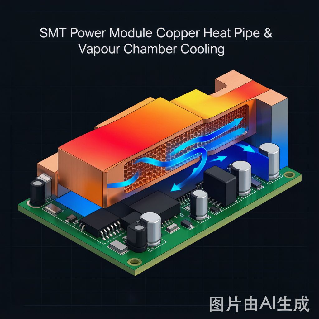
Copper heat pipes and vapor chambers offer a fundamentally different approach to thermal management. Rather than relying solely on conduction through solid metal, these two-phase heat transfer devices exploit the latent heat of vaporization to move heat efficiently from source to sink. A copper heat pipe can transport heat with an effective thermal conductivity 10-100× higher than solid copper, enabling thermal management solutions that are simultaneously more effective and more compact than traditional approaches.
This article examines the operating principles, design considerations, and practical integration of copper heat pipes and vapor chambers in SMT power module applications.
Heat Pipe Operating Principles
A heat pipe is a sealed copper tube containing a working fluid and a capillary wick structure. It transfers heat through a continuous evaporation-condensation cycle:
Evaporator Section: Heat from the power component enters the heat pipe through the copper wall. The working fluid (typically water for electronics cooling) absorbs this heat and evaporates. The evaporation process absorbs the fluid’s latent heat of vaporization — approximately 2,260 kJ/kg for water — providing enormous heat absorption per unit mass.
Adiabatic (Transport) Section: The vapor flows from the evaporator to the condenser through the central vapor space, driven by the pressure gradient created by evaporation at the hot end and condensation at the cold end. This vapor transport is essentially isothermal, meaning the heat pipe can transport heat over significant distances (up to 300mm or more) with a temperature drop of only 1-5°C.
Condenser Section: The vapor reaches the cooler end of the heat pipe, condenses on the copper wall, and releases its latent heat to the heatsink or ambient air. The condensed liquid is then drawn back to the evaporator by capillary action in the wick structure, completing the cycle.
Effective Thermal Conductivity: The effective thermal conductivity of a heat pipe depends on its length, cross-section, and operating conditions, but typical values range from 5,000 to 200,000 W/m·K — compared to 385 W/m·K for solid copper. This extraordinary effective conductivity allows heat pipes to spread heat from a concentrated source across a large heatsink with minimal temperature gradient.
Wick Structures and Their Performance Characteristics
The wick structure is the heart of the heat pipe, providing the capillary pumping force that returns condensate to the evaporator:
Sintered Copper Powder Wick: The most common and versatile wick structure for electronics cooling. Copper powder (50-150 μm particle size) is sintered to the i
er wall of the heat pipe tube, creating a porous structure with high capillary pumping pressure and good thermal contact with the wall. Sintered wicks operate effectively against gravity (evaporator above condenser) up to 10-30cm elevation, depending on pore size and working fluid. They handle heat fluxes up to 50-75 W/cm² in standard configurations.
Grooved Wick: Axial grooves machined or extruded into the i
er wall of the heat pipe. Grooved wicks have lower flow resistance than sintered wicks, enabling longer heat pipe lengths (up to 500mm+). However, their capillary pumping pressure is lower, limiting operation against gravity. Grooved heat pipes are common in laptop cooling where the heat pipe operates horizontally or with the condenser above the evaporator.
Screen/Mesh Wick: Multiple layers of copper or stainless steel screen wrapped inside the heat pipe. Screen wicks offer moderate capillary pressure and are the simplest to manufacture, but they have higher thermal resistance at the wall-to-wick interface compared to sintered wicks. Used primarily in cost-sensitive applications.
Composite Wick: Combines two wick types — typically a fine-pore sintered layer for capillary pumping over a coarse-pore grooved or screen structure for liquid transport. Composite wicks achieve higher capillary pressure and lower flow resistance simultaneously, extending the operating envelope for demanding applications. They are increasingly used in high-performance SMT cooling solutions.
Vapor Chambers: The Two-Dimensional Heat Pipe
A vapor chamber (also called a flat heat pipe or planar heat pipe) extends the heat pipe concept to two dimensions:
Structure: A flat, rectangular enclosure made of copper (typically 2-6mm thick × 30-150mm × 30-150mm), with internal wick structures on the top and bottom walls and vapor space between them. The working fluid (water) fills the wick, and vapor fills the central space.
Operating Principle: Identical to a heat pipe — evaporation at the heat source, vapor transport, condensation at the cold surface, and capillary return. The key difference is that heat spreading occurs in two dimensions rather than along a single axis, making vapor chambers ideal for spreading heat from a concentrated source across a large area.
Thermal Spreading Performance: A vapor chamber can reduce the peak junction temperature by 10-25°C compared to a solid copper spreader of the same thickness and area, depending on the heat source size and power level. This improvement is most dramatic when the heat source is small relative to the spreading area — exactly the situation typical of SMT power modules where a 10mm × 10mm MOSFET die must dissipate heat across a 100mm × 100mm heatsink base.
Weight Advantage: A 3mm thick vapor chamber weighs approximately 30-50% less than a solid copper plate of equivalent area and provides equal or better thermal performance. This weight reduction is significant for automotive and aerospace applications where every gram matters.
Integration into SMT Power Module Designs
Heat pipes and vapor chambers must be mechanically and thermally integrated into the power module assembly:
Direct Attach to Component: The heat pipe or vapor chamber is soldered directly to the power component (MOSFET, IGBT, or GaN die) using a high-temperature solder (SAC305 or Sn/Sb). This provides the lowest possible thermal resistance but requires the heat pipe to survive the solder reflow temperature (up to 260°C for SAC305). Heat pipes with water working fluid are typically limited to 150°C operating temperature, so direct solder attach is feasible only for components with junction-to-case thermal resistance low enough that the case temperature stays below 130°C.
Thermal Interface Material (TIM) Attach: The most common integration method. A thermal grease, gap pad, or phase-change material (PCM) fills the gap between the component and the heat pipe/vapor chamber. This approach is simple, reworkable, and compatible with standard SMT assembly processes. The TIM adds 0.1-0.5°C·cm²/W to the thermal resistance stack, which is acceptable for most power module applications.
Embedded in PCB: For high-density SMT assemblies, heat pipes can be embedded within the PCB stackup. Copper-clad cavities routed into the PCB receive the heat pipe, which is then soldered or thermally bonded in place. This approach saves vertical space but complicates PCB manufacturing and is typically limited to special applications.
Vapor Chamber as Heatsink Base: Replacing a solid copper or aluminum heatsink base plate with a vapor chamber provides dramatic thermal improvement for large-area heatsinks. The vapor chamber spreads heat from the concentrated power component across the entire heatsink base, ensuring uniform fin temperature and maximizing heat dissipation. This is the most cost-effective vapor chamber application for power modules with 50W+ dissipation.
Performance Comparison: Heat Pipe vs Vapor Chamber vs Solid Copper
Understanding the relative performance helps select the right solution:
Heat Spreading from 10mm × 10mm Source to 80mm × 80mm Area (100W):
• Solid Copper, 5mm thick: ΔT ≈ 35-45°C across the spreader
• Vapor Chamber, 3mm thick: ΔT ≈ 5-10°C across the spreader
• Heat Pipe (L-shaped, 8mm diameter × 100mm): ΔT ≈ 3-8°C along the pipe
Weight Comparison for 80mm × 80mm Spreader:
• Solid Copper, 5mm thick: ~285g
• Vapor Chamber, 3mm thick: ~120g (58% lighter)
• Heat Pipe (2× L-shaped, 8mm diameter): ~40g (86% lighter)
Cost Comparison (relative to solid copper = 1.0):
• Solid Copper base: 1.0×
• Vapor Chamber: 3-5× (depending on size and volume)
• Heat Pipe assembly (2 pipes + mounting): 2-4×
The vapor chamber provides the best thermal spreading performance for flat, large-area applications. Heat pipes are more versatile for routing heat around obstacles and to remote heatsinks. Solid copper remains the most cost-effective solution for moderate power levels where the temperature gradient across the spreader is acceptable.
Design Guidelines for SMT Power Module Cooling
Practical design rules for integrating heat pipes and vapor chambers:
When to Use a Heat Pipe: The heat source and heat sink are separated by 30mm+ distance; the thermal path must navigate around obstacles (other components, mounting features); the heat source is concentrated (< 15mm × 15mm) and must be transported to a remote, larger heatsink; the design requires flexibility in thermal routing.
When to Use a Vapor Chamber: A concentrated heat source must be spread across a large-area heatsink; the heatsink base plate temperature gradient exceeds 10°C with solid copper; minimizing Z-height (profile thickness) is a design priority; weight reduction is important (automotive, aerospace).
Orientation Considerations: Heat pipes with sintered wicks operate effectively at any orientation for power levels up to their rated capacity. Grooved wick heat pipes are orientation-sensitive — they perform best with the condenser above the evaporator. Always verify heat pipe performance at the worst-case orientation for the intended application.
Reliability and Lifetime: Copper-water heat pipes and vapor chambers have demonstrated operating lifetimes exceeding 20 years in continuous service, with no measurable degradation in thermal performance. The primary failure mode is non-condensable gas (NCG) generation from copper-water reactions, which blocks the condenser and reduces performance. Quality manufacturers control NCG through rigorous cleaning, processing, and hermetic sealing.
Conclusion
Copper heat pipes and vapor chambers represent the next tier of thermal management capability beyond solid metal heatsinks. Their extraordinary effective thermal conductivity — achieved through two-phase heat transport — enables cooling solutions for SMT power modules that would be impossible with conventional conduction-based approaches.
For power modules dissipating 20-50W from a concentrated source, a vapor chamber integrated as the heatsink base provides a compelling combination of thermal performance, weight reduction, and design simplicity. For higher power levels or when the thermal path must route around obstacles, heat pipes offer versatile, proven solutions.
As SMT power module power densities continue to increase — driven by GaN and SiC wide-bandgap semiconductors pushing switching frequencies and power levels higher — two-phase cooling solutions will move from premium options to standard design practice. The electronics manufacturers who master heat pipe and vapor chamber integration today will be best positioned for the thermal challenges of tomorrow’s power electronics.


