The Rise of Flexible Electronics in Wearable and IoT Devices
The wearable technology and Internet of Things (IoT) markets are experiencing explosive growth, with global wearable device shipments projected to exceed 500 million units a
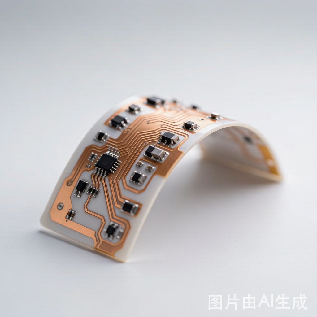
ually. At the heart of these compact, form-factor-driven products lie flexible copper circuits — PCBs built on bendable substrates that enable electronics to conform to curved surfaces, withstand repeated flexing, and fit into spaces impossible for rigid boards.
For SMT (Surface Mount Technology) engineers and designers, flexible circuits present unique challenges and opportunities. The same copper trace that carries signals on a rigid FR-4 board behaves very differently when subjected to dynamic bending on a polyimide substrate.
This guide covers the essential design considerations for flexible copper circuits in wearable and IoT SMT assemblies, from substrate and copper selection to assembly processes and reliability testing.
Substrate Materials: Polyimide vs PEN vs PET
The choice of flexible substrate material significantly impacts circuit performance, cost, and durability:
Polyimide (PI): The gold standard for high-reliability flexible circuits. Polyimide offers excellent thermal stability (up to 260°C for soldering), good dielectric properties, and outstanding flex endurance. Thickness ranges from 12.5μm to 125μm.
Polyethylene Naphthalate (PEN): A cost-effective alternative with lower thermal resistance (up to 150°C). Suitable for low-temperature SMT processes and static flex applications. Often used in consumer wearables and disposable medical sensors.
Polyethylene Terephthalate (PET): The lowest-cost option, primarily used for simple flex circuits, ante
as, and disposable electronics. Limited to processing temperatures below 120°C.
For wearable devices that require repeated dynamic flexing and standard SMT soldering, polyimide is overwhelmingly the preferred choice. Its combination of thermal stability, mechanical durability, and chemical resistance makes it suitable for demanding applications.
Copper Foil Selection for Flexible Circuits
Flexible circuits use two primary types of copper foil, each with distinct characteristics:
Rolled A
ealed (RA) Copper: The preferred choice for dynamic flex applications. RA copper has a horizontal grain structure that resists fatigue cracking under repeated bending. Available in 12μm, 18μm, and 35μm thicknesses. RA copper typically withstands 100,000+ flex cycles at a 5mm bend radius.
Electrodeposited (ED) Copper: Features a vertical columnar grain structure that is stronger in the Z-axis but less tolerant of dynamic flexing. ED copper is less expensive and provides higher tensile strength, making it suitable for static flex (bend-to-install) applications.
For wearable devices that undergo continuous movement (smartwatch bands, fitness sensors, medical patches), RA copper is strongly recommended. Thi
er copper (12-18μm) provides better flexibility at the cost of higher DC resistance.
Adhesiveless laminates (direct bond of copper to polyimide) are preferred for high-density flex circuits because they offer better dimensional stability and finer etch capability compared to adhesive-based constructions.
Trace Design Rules for Flexible SMT Circuits
Designing copper traces on flexible substrates requires specific rules that differ from rigid PCB design:
Trace Width and Spacing: Minimum trace/space for polyimide flex is typically 50μm/50μm (2/2 mil) with advanced etching. For standard designs, use 100μm/100μm or wider for better manufacturability.
Bend Radius Guidelines: The minimum static bend radius should be at least 6× the total laminate thickness. For dynamic flexing, maintain a minimum radius of 10× thickness.
Hatched Ground Planes: Instead of solid copper pour on flex regions, use hatched ground planes (crosshatched copper pattern) to reduce stiffness and prevent copper wrinkling during bending.
Strain Relief at Transition Zones: Where the flexible section meets a rigid section or component mounting area, provide gradual transitions. Fillet the copper traces and add coverlay openings with rounded corners to prevent stress concentration.
SMT Assembly on Flexible Circuits: Special Considerations
Mounting components on flexible circuits requires adapted SMT processes:
Board Fixturing: Flexible circuits must be held flat during solder paste printing, pick-and-place, and reflow. Custom fixtures (carriers) made from aluminum or composite materials with vacuum hold-down or mechanical clamping are essential.
Solder Paste Printing: Use stencils specifically designed for flexible circuits, accounting for any substrate compression in the fixture area. Paste release can be challenging on thin polyimide substrates, so verify print quality with SPI (Solder Paste Inspection).
Reflow Profile: Polyimide substrates absorb less heat than FR-4, so peak temperatures may be reached faster. Use a slightly lower peak temperature (235-240°C for SAC305) with appropriate soak time to ensure complete wetting without overheating.
Component Selection for Flex: Use thi
er, smaller components where possible. Chip-scale packages (CSP), 0201 passives, and flexible IC packages are ideal. Avoid large, heavy components in areas that will be dynamically flexed.
Coverlay and Solder Mask Alternatives
Protecting copper traces on flexible circuits uses different materials than rigid boards:
Flexible Solder Mask: Liquid photoimageable (LPI) solder mask can be applied to flex circuits but may crack under repeated bending. Suitable for areas that do not flex.
Coverlay (Polyimide Film): The traditional protection method for flexible circuits. A thin layer of polyimide film with adhesive is laminated over the copper traces, with openings laser-drilled for solder pads. Coverlay provides excellent flexibility and durability.
Flexible Solder Mask (Dry Film): Newer dry film solder mask products offer better flexibility than LPI while providing finer resolution than coverlay. These are increasingly popular for high-density flex circuits.
Reliability Testing for Flexible SMT Assemblies
Wearable and IoT flexible circuits must undergo rigorous reliability testing:
Dynamic Flex Testing: Cycling the circuit through thousands of bend cycles (typically 100,000+) at the designed bend radius while monitoring continuity. IPC-6215 provides test methods for flexible circuit reliability.
Environmental Testing: Temperature cycling (-40°C to +85°C for consumer, -55°C to +125°C for industrial), humidity exposure, and salt spray testing for outdoor wearables.
Solder Joint Integrity: Shear and pull testing of SMT components on flex substrates, particularly after flex cycling. Copper pad adhesion to polyimide should be verified per IPC-6013 Class 3 requirements.
Accelerated Life Testing: Combined environmental and mechanical stress testing to predict long-term reliability in real-world conditions.
Conclusion
Flexible copper circuits are enabling the next generation of wearable technology and IoT devices. By understanding the unique properties of polyimide substrates, rolled a
ealed copper, and the specific SMT assembly requirements for flexible circuits, engineers can design reliable products that meet the demanding requirements of dynamic flexing environments.
As flexible electronics technology continues to evolve with thi
er materials, higher copper densities, and more robust assembly processes, the opportunities for i
ovative wearable and IoT products will only expand. The design principles outlined in this guide provide a practical foundation for developing flexible SMT assemblies that perform reliably in real-world applications.


