Automated Optical Inspection (AOI) is a non-contact quality control technology that uses camera systems and image processing algorithms to detect PCB assembly defects. In modern SMT production, AOI is indispensable for maintaining product quality at high production volumes.
How AOI Works
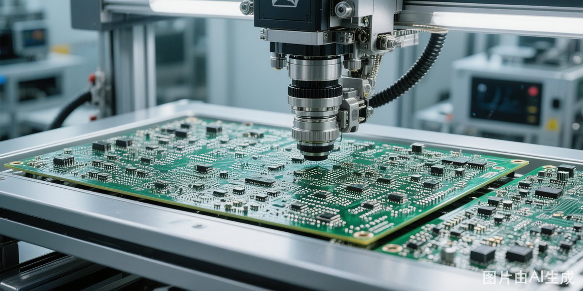
AOI systems capture images of the PCB assembly using one or more cameras and multiple lighting configurations (top-down, angled, colored LEDs). Image processing software then compares these images against a reference “golden board” or programmed inspection rules to detect anomalies in component presence, position, orientation, solder joint quality, and PCB markings.
Types of Defects AOI Can Detect
- Missing components: Component not placed on pad.
- Wrong component: Incorrect value or part number placed.
- Misalignment: Component shifted or rotated from correct position.
- Tombstoning: One end of component lifted off pad.
- Solder bridges: Unintended solder co
ections between adjacent pads.
- Insufficient solder: Solder joints with too little solder material.
- Excess solder (solder balls): Solder balls or splatter on board surface.
- Reversed polarity: Diodes, electrolytic capacitors, or ICs placed backwards.
- Lifted leads: IC leads not making contact with pads.
2D vs 3D AOI Systems
Traditional 2D AOI systems capture top-down images and are suitable for detecting presence/absence and gross misalignment. 3D AOI systems add height measurement using laser profilometry or structured light, enabling detection of lifted leads, insufficient solder volume, and co-planarity issues. For high-reliability applications, 3D AOI provides significantly better defect coverage.
Placement of AOI in the SMT Line
- Post-paste AOI (SPI): Inspects solder paste deposition before component placement. Catches printing defects early.
- Pre-reflow AOI: Checks component placement and polarity before soldering. Prevents rework of soldered boards.
- Post-reflow AOI: Inspects completed solder joints. Most common AOI position in SMT lines.
- Post-wave solder AOI: For through-hole and mixed assembly boards.
Programming and Optimizing AOI
Effective AOI requires well-programmed inspection libraries and properly set thresholds. Too tight tolerances cause false failures (pseudo-errors) that slow production; too loose tolerances allow real defects to pass. Regular correlation studies between AOI escape rates and downstream inspection (X-ray, ICT, functional test) help optimize inspection parameters over time.
Integration with SPC and MES
Modern AOI systems integrate with Statistical Process Control (SPC) software and Manufacturing Execution Systems (MES) to provide real-time trend analysis and process control. When a particular defect type begins trending upward, the system can alert operators and even feed corrections back to upstream equipment like printers or pick-and-place machines.
TechMart SE provides a comprehensive range of SMT inspection consumables and accessories to support your quality assurance processes. From calibration standards to replacement cameras and lighting modules, we have what your AOI systems need to perform at their best.


