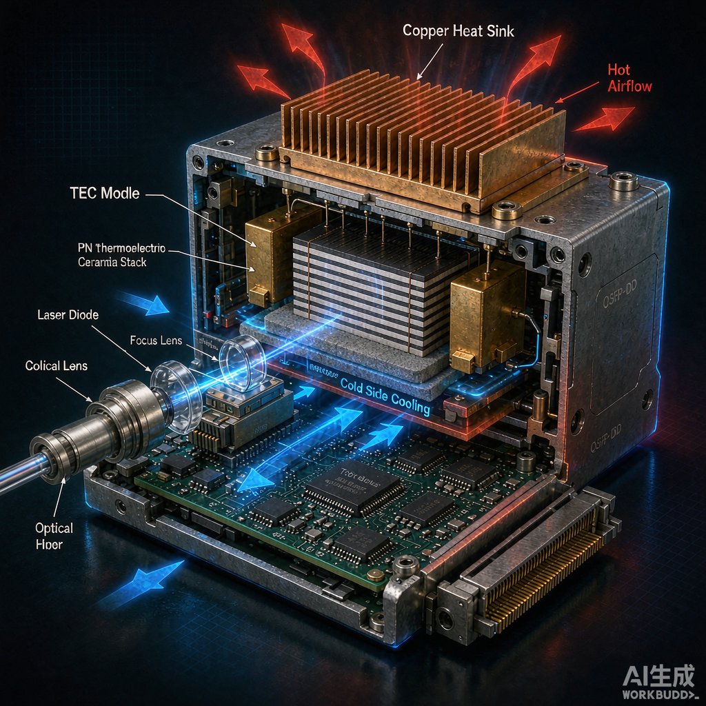
The Thermal Challenge in Optical Transceivers
100G/400G/800G optical transceivers pack DFB, EML, or silicon photonics lasers alongside DSPs and drivers into a QSFP-DD or OSFP form factor. Laser wavelength drifts approximately 0.08–0.1 nm/°C, making ±0.1°C temperature stability essential for DWDM cha
el alignment. When ambient air cooling is insufficient, thermoelectric coolers (TECs) provide active, precise temperature control.
How TECs Work
A TEC module uses the Peltier effect: DC current drives heat from the cold side (laser submount) to the hot side (heat sink). Key parameters include:
- ΔT_max: Maximum temperature difference between sides at zero heat load (typically 60–72°C for Bi₂Te₃ modules).
- Q_max: Maximum heat pumping capacity at ΔT = 0 (watts).
- COP (Coefficient of Performance): Ratio of heat pumped to electrical input power. COP peaks at 30–50% of I_max and drops as ΔT increases.
Sizing a TEC for a Transceiver
Follow this design sequence:
- Calculate heat load (Q_c): Sum laser dissipation (~0.5–2 W), TOSA heater (if any), and conductive losses through leads and submount.
- Define temperature targets: Cold-side temperature (T_c, e.g., 25°C) and maximum hot-side temperature (T_h, e.g., 65°C), giving ΔT = 40°C.
- Select Q_max: Choose a TEC with Q_max ≥ 1.5× Q_c at the operating ΔT to account for COP degradation and aging.
- Verify power budget: TEC input power = Q_c / COP. At COP ≈ 0.5, a 1.5 W load requires ~3 W electrical—significant in a 12 W total QSFP-DD budget.
Hot-Side Heat Sink Design
The TEC merely moves heat; it does not eliminate it. A undersized hot-side heat sink causes T_h to rise, reducing ΔT capability and potentially causing thermal runaway. Guidelines:
- Thermal resistance target: R_th ≤ (T_h − T_ambient) / (Q_c + P_tec). For T_h = 65°C, T_amb = 45°C, and total = 4.5 W, R_th ≤ 4.4 K/W.
- Heat sink type: Vapor chamber or copper skived fins with forced air (1–2 m/s) are common in OSFP cages.
- TIM selection: Phase-change materials (e.g., 55°C transition) between TEC and heat sink improve contact conductance compared to grease.
Control Strategy: PID vs On-Off
Simple on-off control creates temperature oscillations that degrade laser linewidth. A PID controller with PWM drive (1–10 kHz) is standard:
- P term: Fast response to setpoint changes; too high causes overshoot.
- I term: Eliminates steady-state offset from ambient drift.
- D term: Dampens oscillation; critical in systems with thermal mass < 1 J/K.
Some designs add a feed-forward term based on measured laser current, anticipating heat load changes before they affect temperature.
SMT Assembly and Reliability
TEC modules are traditionally hand-soldered or clamped, but micro-TEC arrays are now compatible with SMT reflow:
- Solder: BiSn or InSn low-temperature alloys prevent Bi₂Te₃ degradation (max 200°C for < 3 min).
- CTE matching: Alumina ceramic substrates (TEC) and AlN laser submounts (CTE ~ 4.5 ppm/K) minimize shear stress.
- Power cycling: TECs are the dominant failure mechanism in cooled transceivers. Accelerated life tests apply 500,000+ power cycles to verify solder joint integrity.
Alternative and Complementary Approaches
TEC integration is not always necessary:
- Uncooled DFBs: Wider cha
el spacing (e.g., CWDM4) tolerates ±5°C drift, eliminating TEC entirely.
- Silicon photonics: Ring modulators are more temperature-sensitive than DFBs, but integrated heaters (resistive thin film) offer faster response than TECs with lower power.
- Thermal interface optimization: Sometimes improving TIM between laser and package lid reduces junction temperature enough to avoid active cooling.
Conclusion
TECs enable sub-degree temperature stability in high-performance optical transceivers, but their power consumption, size, and reliability cost must be justified by the wavelength precision required. Careful sizing of Q_max, hot-side thermal resistance, and closed-loop control determines whether the TEC is an asset or a liability in the thermal budget.



