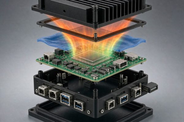
Medical electronic devices fail EMC testing for reasons that are almost never on the schematic. A monitor with 40 dB of shielding effectiveness at 1 GHz still fails radiated immunity at 3 V/m because a seam gasket was compressing to 20 percent instead of 40, or because a display flex cable crosses the shield boundary without a filter. IEC 60601-1-2 fourth edition raised both emissions and immunity requirements, and it asks for something commercial standards do not: a risk management file that explains what happens to the patient when interference occurs.
What the Standard Actually Demands
IEC 60601-1-2 edition 4.1 aligns emissions with CISPR 11 for Group 1 equipment, which covers most monitoring, imaging and laboratory devices. Class B limits apply to home healthcare and to devices used in residential environments; Class A applies to professional healthcare facilities. The difference at 30 to 230 MHz is 10 dB, which is the difference between one shield design and another.
Immunity levels worth designing to
- Radiated RF immunity: 3 V/m from 80 MHz to 2.7 GHz, 10 V/m in the professional healthcare environment profile
- Proximity fields from wireless transmitters: 9 V/m at 710/745/780/5240/5550/5785 MHz, 28 V/m for 385/450/810/870/930/1720/1845/1970/2450 MHz services
- Conducted RF immunity: 3 V RMS, 150 kHz to 80 MHz
- ESD: 8 kV contact, 15 kV air, with the 2014 amendment accepting 8 kV air in some cases
- Power frequency magnetic field: 30 A/m
- Voltage dips and short interruptions down to 0 percent for 5 seconds, which forces hold-up design
The proximity field requirement is the one that surprises designers. A 2 W handheld radio at 0.15 m produces field strengths far above 10 V/m, so the test emulates a transmitter placed directly against the device. Front-end circuitry must tolerate it without latching, resetting or producing artefact in a physiological waveform.
Emissions: Find the Source Before You Shield
Switching supplies and gate drive
A 100 to 300 kHz flyback with 20 ns switching transitions generates harmonics that stay strong past 100 MHz. Slow the gate, add an RC snubber across the primary switch, and keep the primary loop area under 2 cm squared. These three changes often buy 6 to 12 dB and cost nothing.
Clock and display interfaces
MIPI DSI and LVDS run at hundreds of megabits per second and their harmonics land squarely in the immunity test bands. Route them on the i
er layers with a continuous reference plane, keep the differential pair skew under 5 ps, and place a common mode choke at the co
ector if the cable is longer than 50 mm. A flex cable that leaves the shielded volume without filtering is a guaranteed failure at 700 MHz to 1 GHz.
The 2.4 and 5 GHz coexistence problem
Many devices now include WiFi or Bluetooth for data upload. Their own radios are legitimate emissions, but the module’s harmonics and the coexistence spurs can still breach CISPR 11 limits. Test with the radio transmitting at maximum power in every supported mode, because a device that passes with WiFi idle and fails under load is a common and embarrassing finding.
Mechanical Shielding Design
Seams are the dominant leak
Shielding effectiveness of a solid enclosure at 1 GHz is well over 80 dB. Real assemblies land at 35 to 55 dB because of seams, and seam performance is set by the longest unbroken gap, not by total gasket length. Use the lambda over 20 rule: the longest aperture dimension must stay below one twentieth of the shortest wavelength of concern. At 2.7 GHz, wavelength is 111 mm, so treat 5.5 mm as the ceiling for a gap. That means screw spacing of 20 to 30 mm and a continuous conductive gasket, not a few clips.
Gasket compression and material
Specify compression between 20 and 50 percent of free height, and verify that the flange is stiff enough to keep that range across its span. A 0.8 mm steel cover spa
ing 150 mm deflects visibly between fasteners; add a stiffening rib or reduce screw pitch.
Choose filler by galvanic compatibility with the housing finish. Silver-plated aluminium or silver-plated glass in silicone works against nickel-plated ABS or chromate conversion coated aluminium. Nickel-graphite is the economical choice where 40 to 60 dB is enough. Avoid pairing silver filler with bare aluminium in humid air unless the joint is sealed, because the couple corrodes and contact resistance climbs within months.
Displays, vents and co
ectors
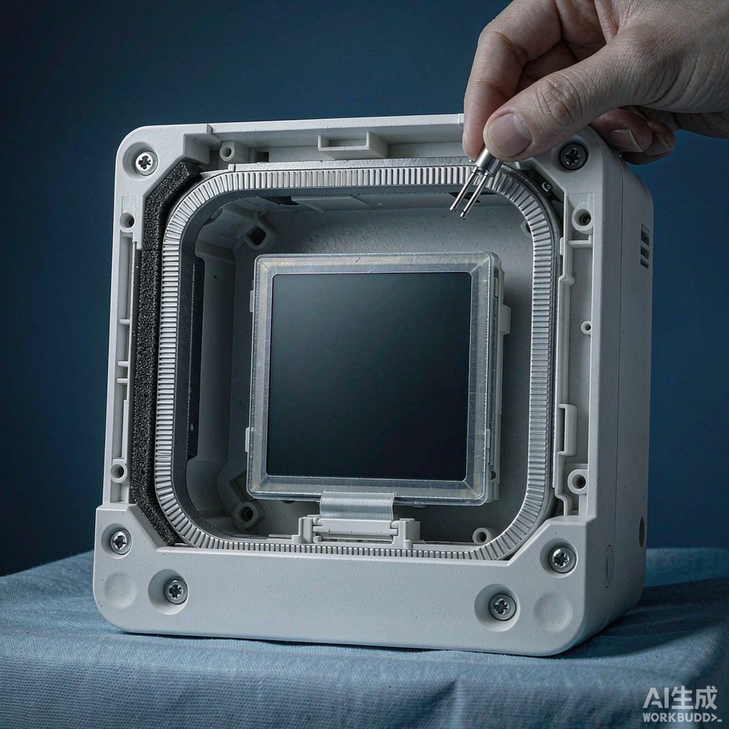
A display is a hole in the shield. Options, in ascending cost: an ITO coated window at 20 to 30 dB with 80 percent transmission, a fine metal mesh laminated between glass layers at 40 to 60 dB with 70 percent transmission, or a conductive gasket ring bonded to the display bezel. Whatever you choose, the conductive layer must terminate around its full perimeter to the chassis, with conductive foam or a finger stock ring, not with two grounding tabs.
Vents need honeycomb with a depth to aperture ratio above 3, and the honeycomb frame must bond electrically to the panel. Cable entry points need either shielded co
ectors with 360 degree backshell termination or feedthrough filters, never a pigtail.
Patient-Co
ected Leads Need Different Treatment
Any lead that touches a patient is both an ante
a and a safety path. Filtering must satisfy two constraints at once: enough attenuation to keep RF out of the front end, and low leakage current at power line frequency, typically 10 microamperes for patient-co
ected parts and 50 to 100 microamperes for enclosure leakage.
Use a two-stage approach. A common mode choke at the co
ector handles the differential to common conversion, followed by an RC or LC low pass with a cutoff at one tenth of the lowest interference frequency of concern, typically 8 to 15 MHz. Series resistors in the lead path also limit current if the patient becomes a coupling path. Verify with a leakage current tester per IEC 60601-1 clause 8.7 after filtering; adding capacitance to a patient lead is the classic way to fail the safety test while passing the EMC test.
Documentation Is Part of the Submission
Edition 4 requires an EMC risk assessment. For each immunity test, document the foreseeable interference, the resulting device behaviour, and the risk control. A monitor that briefly shows artefact during a 15 kV air discharge may be acceptable if the artefact self-clears within two seconds and does not obscure a rhythm; a device that resets its alarm limits is not.
Build the test plan around the actual clinical environment. A device used in an MRI suite faces a different field profile than one used in a home. Then run pre-compliance scans with a near-field probe set and a spectrum analyser at least twice before the accredited lab, because a failed formal test costs both a re-test fee and a schedule slip measured in weeks.