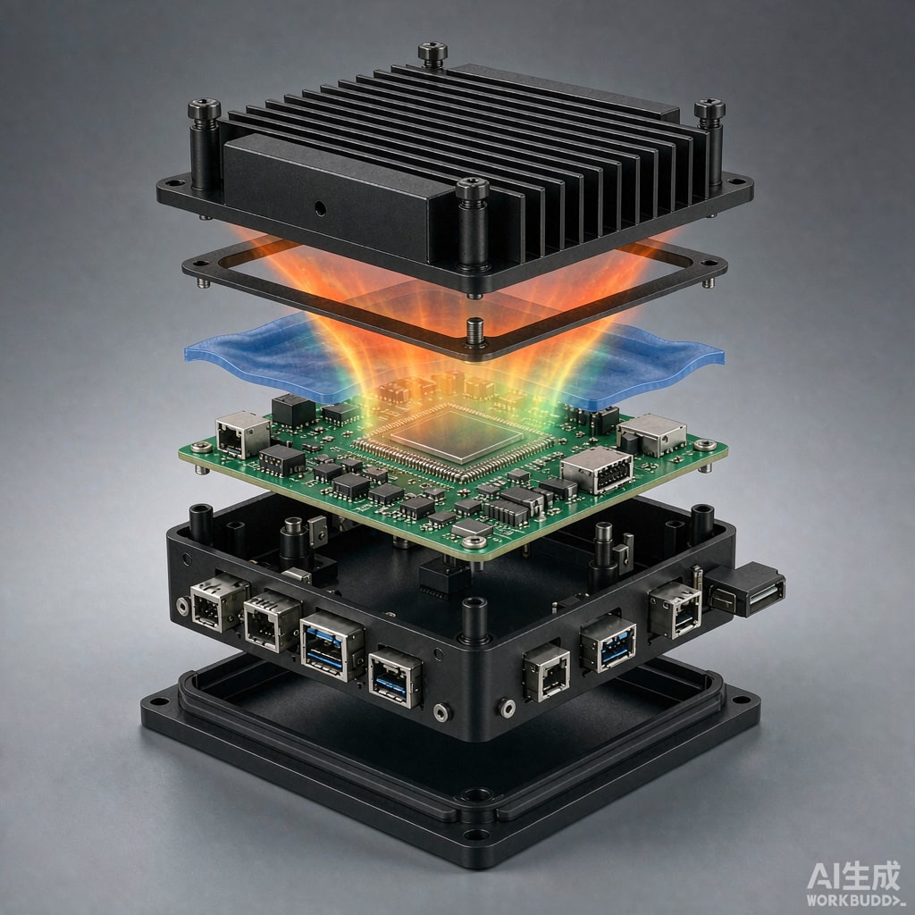
Edge inference boxes are specified like computers and installed like appliances. A 25 to 60 W system on a chip, 16 GB of LPDDR, two NVMe drives and a 2.5 GbE PHY get folded into a sealed aluminium enclosure with an IP54 gasket, mounted inside a roadside cabinet where the air reaches 45 degrees C in the afternoon. There is no fan, no vent and no maintenance access. Thermal design is the entire reliability story of the product.
Start With an Honest Heat Budget
Datasheet thermal design power is not the number you need. For inference workloads the useful figure is sustained power over a ten minute window, which for a modern edge SoC is often 60 to 80 percent of peak TDP once DVFS settles. A representative budget for a 30 W class box:
- SoC at sustained inference: 22 to 28 W, with 100 ms spikes to 45 W
- LPDDR5: 2 to 3 W, mostly at the memory controller
- Two NVMe drives: 3 to 6 W each under sustained write
- 2.5 GbE PHY plus magnetics: 1.5 to 2.5 W
- Buck converters and LDOs: 1.5 to 3 W, with hotspots at the switch node
- PoE or wide-input front end: 2 to 4 W if the box is powered over Ethernet
Total lands near 40 W. Add 15 percent margin for component variation and dust-blinded surfaces, and design the enclosure for 46 W. Everything downstream depends on this number being pessimistic rather than optimistic.
The Real Bottleneck Is Spreading Resistance
A 20 by 20 mm die dissipating 25 W produces a heat flux of 6.25 W/cm squared. Getting that flux out of the package is the easy part; getting it to spread across a 200 by 150 mm enclosure wall is not. Spreading resistance dominates whenever the heat source area is much smaller than the sink area, and it scales inversely with the square root of the spreader area and inversely with thickness.
The numbers that matter
For a 3 mm aluminium base with 200 W/mK conductivity, spreading resistance from a 20 mm source typically lands at 0.35 to 0.55 K/W. At 25 W that is 9 to 14 K of temperature rise before the heat has even reached the outside air. Doubling base thickness to 6 mm reduces spreading resistance by roughly 25 percent, not 50, because you hit diminishing returns once the Biot number drops.
Practical consequences: keep the SoC directly under the largest flat external surface, never on a bracket, and never centred on a thin wall next to a plastic window. If the mechanical layout forces a remote position, do not thicken the base indefinitely; insert a heat pipe or vapour chamber to move the flux with an effective conductivity of 5000 to 20000 W/mK instead of 200.
Where the die sits relative to the wall
Orientation matters more than most layouts admit. Mount the SoC on the underside of a top-mounted enclosure so the heat rises into the lid, or on the side that faces away from the sun if the box is outdoors. Vertical mounting with fins on the shaded face outperforms horizontal mounting by 10 to 20 percent in natural convection because the boundary layer stays thi
er.
Turning the Enclosure Into a Heat Sink
Fin geometry for natural convection
Natural convection wants wide spacing and short fins. Use 8 to 12 mm pitch, 20 to 35 mm fin height, and 1.5 to 2.5 mm fin thickness in aluminium extrusion. Tighter pitch looks better on a datasheet and performs worse, because the boundary layers merge and the i
er cha
els stall. Chamfered or rounded fin tips and a 5 degree draft help plume development.
Surface finish is not cosmetic
In still air, radiation carries 25 to 40 percent of the heat load at these temperatures. Black anodising raises emissivity from roughly 0.1 for bare mill finish to 0.85, which is worth 4 to 8 K at 25 W. Avoid polished or bright chromate finishes on the external surface; they buy corrosion resistance and cost you radiating area.
IP54 does not mean sealed against heat
A gasket keeps dust out but also traps internal air. Internal natural circulation will still work: cool air falls along the walls, rises over the SoC, and loops. Blocking that loop with a full-length PCB or a cable bundle creates a stagnant pocket that runs 10 to 15 K hotter than the rest of the volume. Leave 10 mm clearance above the SoC and stagger card guides.
The Interface Between Die and Wall
A gap of 0.1 mm filled with air costs about 4 K/W per square centimetre, which at 25 W over 4 cm squared is catastrophic. Fill it properly.
Material choice
For permanent assembly, a 1.0 to 2.0 mm soft silicone gap filler at 2 to 4 W/mK absorbs tolerance stack-up and survives vibration. For a serviceable design, a phase change material at 3 to 8 W/mK gives thin bond lines and reworkability. Grease is the best performer per micrometre but pumps out under thermal cycling in a vertical orientation, and a fanless box has no fan vibration to redistribute it. Avoid it in this application.
Pressure, not just contact
Contact resistance falls steeply between 10 and 50 kPa and flattens above 100 kPa. Use four screws around the SoC, not two, and specify a spring-loaded heat spreader plate or a standoff that limits compression to 30 to 50 percent of pad thickness. Measure with pressure-sensitive film on the first article; uneven pressure is the single most common cause of a hotspot on an otherwise correct design.
Derating the Parts Nobody Watches
The SoC has a thermal throttling path. The eMMC, the PHY and the buck inductors do not.
- eMMC and UFS: case temperature limit typically 85 degrees C, with data retention degrading above 70 degrees C. Place away from the SoC, ideally near a wall.
- LPDDR: 85 degrees C case limit, and refresh rate must double above 85 degrees C to avoid bit errors. Keep the memory controller region in the airflow path, not in a corner.
- Electrolytic capacitors: every 10 K above rated temperature halves life. If any exist in the power path, move to polymer or ceramic.
- 2.5 GbE magnetics and crystals: 5 to 10 ppm drift over temperature can break timing budgets at the edges of the standard.
- Battery or supercapacitor for RTC hold-up: 60 degrees C is often the hard ceiling.
Validation That Means Something
Bench testing at 25 degrees C in open air proves nothing. Build a chamber test at the specified maximum ambient, 45 or 55 degrees C, with the box in its installed orientation and the cabinet door closed. Run the real inference workload, not a synthetic CPU burn, for at least 60 minutes and log SoC junction temperature, package case temperature, wall temperature at three points, and internal air temperature at two heights.
Acceptance criteria should be explicit: junction temperature below the throttle point minus 10 K, all component case temperatures below datasheet limits minus 10 K, external touch surface below the safety limit for the application, and no thermal throttling in the log. Then repeat at 85 percent relative humidity to check for condensation on the cold wall during the first ten minutes of power-up after a cold soak. A fanless box that passes the temperature test and fogs internally still fails in the field.



