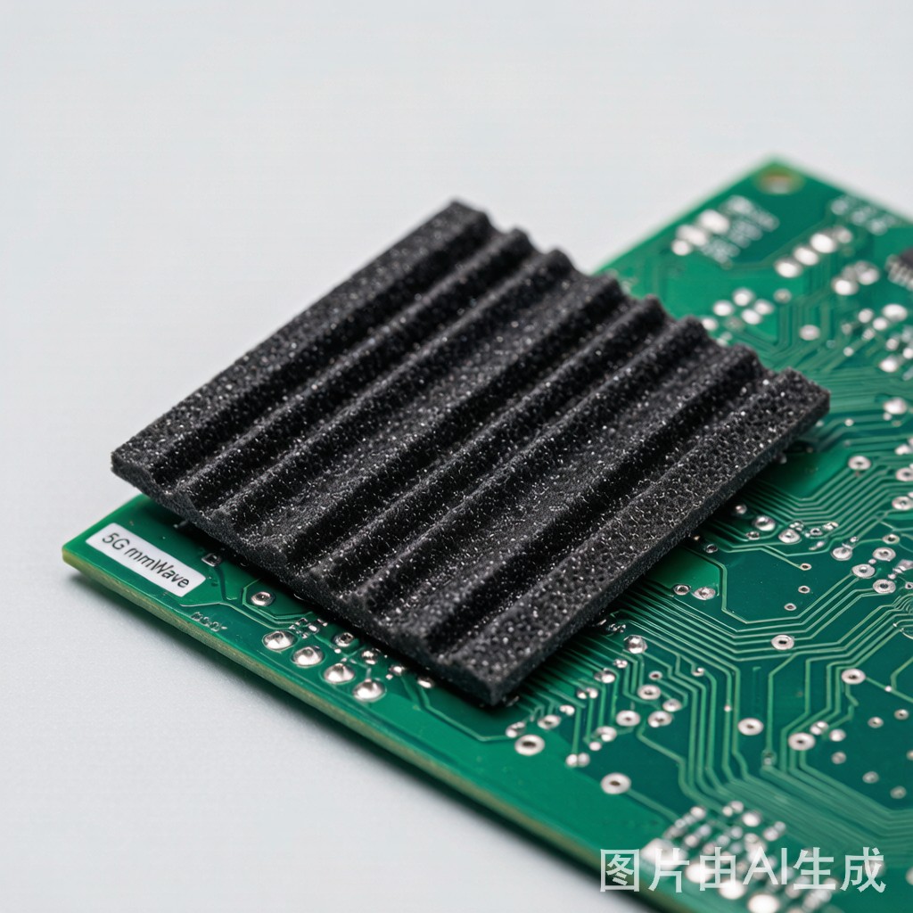
The Thermal-EMI Coupling Problem in 5G mmWave
5G customer-premises equipment, small cells, and automotive radar modules pack high-power RF amplifiers next to sensitive transceivers. Heat must leave the enclosure, but every aperture, gap, and thermal pad is a potential electromagnetic leakage path. Traditional metal shields block EMI but trap heat; thermal pads conduct heat but do nothing for noise. Thermally conductive EMI absorbers bridge both functions by converting incident RF energy into heat while conducting waste heat toward the housing.
Material Classes: Ferrite-Filled Silicone, Carbon-Based Absorbers, and Ceramic Composites
Ferrite-filled silicone sheets
These combine NiZn or MnZn ferrite powders in a silicone matrix. They offer broadband absorption from 1 GHz to 18 GHz, compression set resistance, and easy die-cutting. Typical thermal conductivity is modest (0.8–1.5 W/m·K), so they work best when the heat flux is low or paired with a metal spreader.
Carbon-based absorbers
Carbon-fiber fabric, graphite flakes, and carbon-silicone blends provide higher thermal conductivity (1.5–6 W/m·K) and strong absorption across 5–40 GHz. They are preferred for mmWave modules where dielectric losses are tuned to the 24 GHz, 28 GHz, or 77 GHz bands.
Ceramic-filled composites
Boron nitride or alumina fillers in a polymer binder deliver the highest thermal conductivity (3–8 W/m·K) but narrower absorption bandwidth. These are used when heat dominates and EMI is a secondary concern, often layered with a thin ferrite sheet.
Key Metrics: Thermal Conductivity, Insertion Loss, and Compression Set
| Metric | Typical Range | Why It Matters |
|---|---|---|
| Thermal conductivity | 0.8–8 W/m·K | Higher values reduce junction temperature rise |
| Insertion loss | 5–25 dB | Defines how much RF energy is absorbed at target frequency |
| Compression set | 5 %–30 % | Long-term contact pressure after thermal cycling |
| Dielectric constant (Dk) | 3–12 | Impacts ante
a desense and near-field coupling |
Frequency Targeting: Sub-6 GHz vs mmWave Bands
Absorber performance peaks where magnetic or dielectric loss is maximized. For sub-6 GHz baseband and LTE coexistence, MnZn ferrite sheets with high permeability work well. For 28 GHz and 39 GHz 5G NR, thi
er carbon-loaded absorbers (0.2–0.5 mm) with tuned Dk and Df are more effective because they place the loss peak in the millimeter-wave range.
Always request swept-frequency insertion-loss data from your supplier rather than relying on a single-point rating. A material rated “10 dB at 10 GHz” may drop to 3 dB at 28 GHz.
Application Guidelines and Design Checklist
- Place absorbers directly over noise sources such as PA modules and power inductors.
- Maintain ≥20 % compression to ensure thermal and electrical contact without over-stressing the material.
- Ground any metal carrier layer to the chassis to prevent re-radiation.
- Avoid blocking intentional ante
a apertures; use absorber only in shielded cavities.
- Verify outgassing and UL 94 flammability ratings for sealed outdoor enclosures.
Thermally conductive EMI absorbers let RF engineers solve two problems with one material, reducing stack-up thickness and assembly cost in compact 5G hardware.



