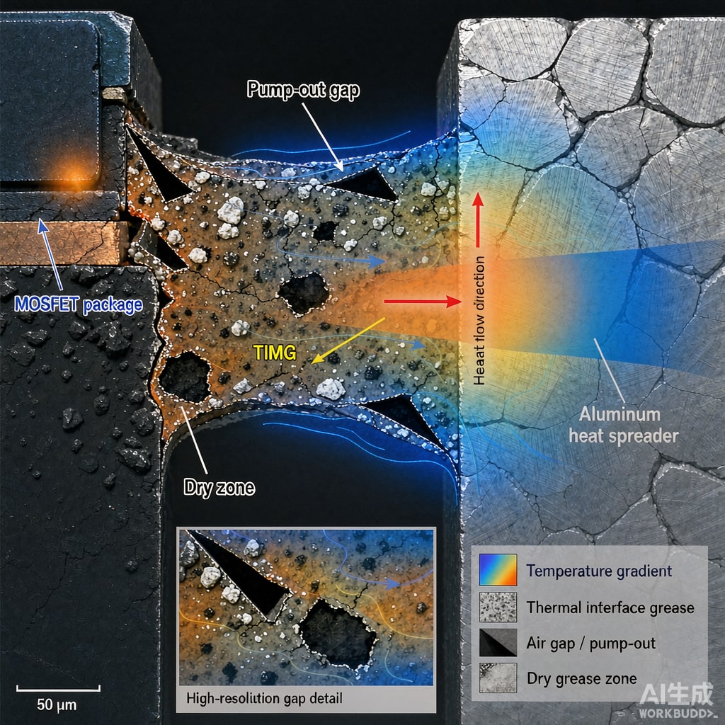
A power MOSFET, IGBT, or RF device can look perfectly mounted and still overheat because the thermal interface material between the package and the heat spreader has degraded. The two most common long-term failure modes are pump-out and dry-out. Both raise thermal resistance, push junction temperature higher, and shorten component life. For SMT power modules that are expected to last ten or fifteen years, understanding these mechanisms is as important as selecting the right heat sink.
What Is TIM Pump-Out?
Pump-out happens when the assembly undergoes thermal cycling. The package and heat spreader expand and contract at different rates because their coefficients of thermal expansion differ. Each cycle squeezes the thermal grease outward from the center of the interface and draws it back imperfectly. Over hundreds or thousands of cycles, the grease migrates to the edges, leaving a dry center with high contact resistance. The effect is strongest with soft, low-viscosity silicones and large die areas. Modules in automotive, solar inverter, and base-station applications are especially vulnerable because they see wide daily temperature swings.
Symptoms of Pump-Out
Early signs include a gradual rise in case temperature under load and an increase in thermal resistance measured with a transient tester. In severe cases, the device enters thermal shutdown during peak load even though the heat sink and airflow are unchanged. Visual inspection sometimes shows grease squeezed beyond the package footprint.
What Is TIM Dry-Out?
Dry-out is the loss of volatile components from the grease or phase-change material at elevated temperature. As the oil fraction evaporates or separates, the remaining filler matrix becomes stiff and cracked. The interface no longer conforms to surface roughness, and air gaps appear. Dry-out accelerates above the continuous-use temperature of the compound. A 150°C-rated grease operated at 140°C may last years; the same grease operated at 160°C can dry within months.
Selecting Stable Thermal Interface Materials
Material selection should match the module’s operating temperature, cycling severity, and lifetime target. Options include:
- High-consistency silicone greases with low bleed and low volatility: good general choice for consumer and industrial power supplies
- Phase-change materials: soften above their melt point to fill gaps, then solidify; less prone to pump-out than soft grease but must stay below their upper temperature limit
- Thermal gap pads and putties: physically constrained by compression; no pump-out, but higher thermal resistance than thin grease layers
- Graphite or metal-based phase-change pads: stable at high temperature and large area; common in EV inverters and server CPUs
Application Rules That Extend TIM Life
Even a stable material fails if applied incorrectly. Apply a thin, uniform layer — typically 0.05–0.15 mm wet — using screen printing or a pattern that minimizes trapped air. Mounting pressure should be even across the package; a clip or spring load is better than a rigid screw torque because it accommodates thermal expansion. Avoid overhanging the grease beyond the footprint, since that promotes pump-out cha
els.
Validation and Screening
Screen candidate TIMs with accelerated thermal cycling and thermal resistance measurements. A common screen is 1,000 cycles from −40°C to +125°C or +150°C, measuring Rθ before and after. If Rθ increases more than 10–20%, the material is unlikely to survive the product life. For critical power modules, also run high-temperature storage at the maximum junction temperature for 500–1,000 hours and check for weight loss and hardness change. These tests cost time but are far cheaper than a field recall caused by a dried-out thermal joint.



