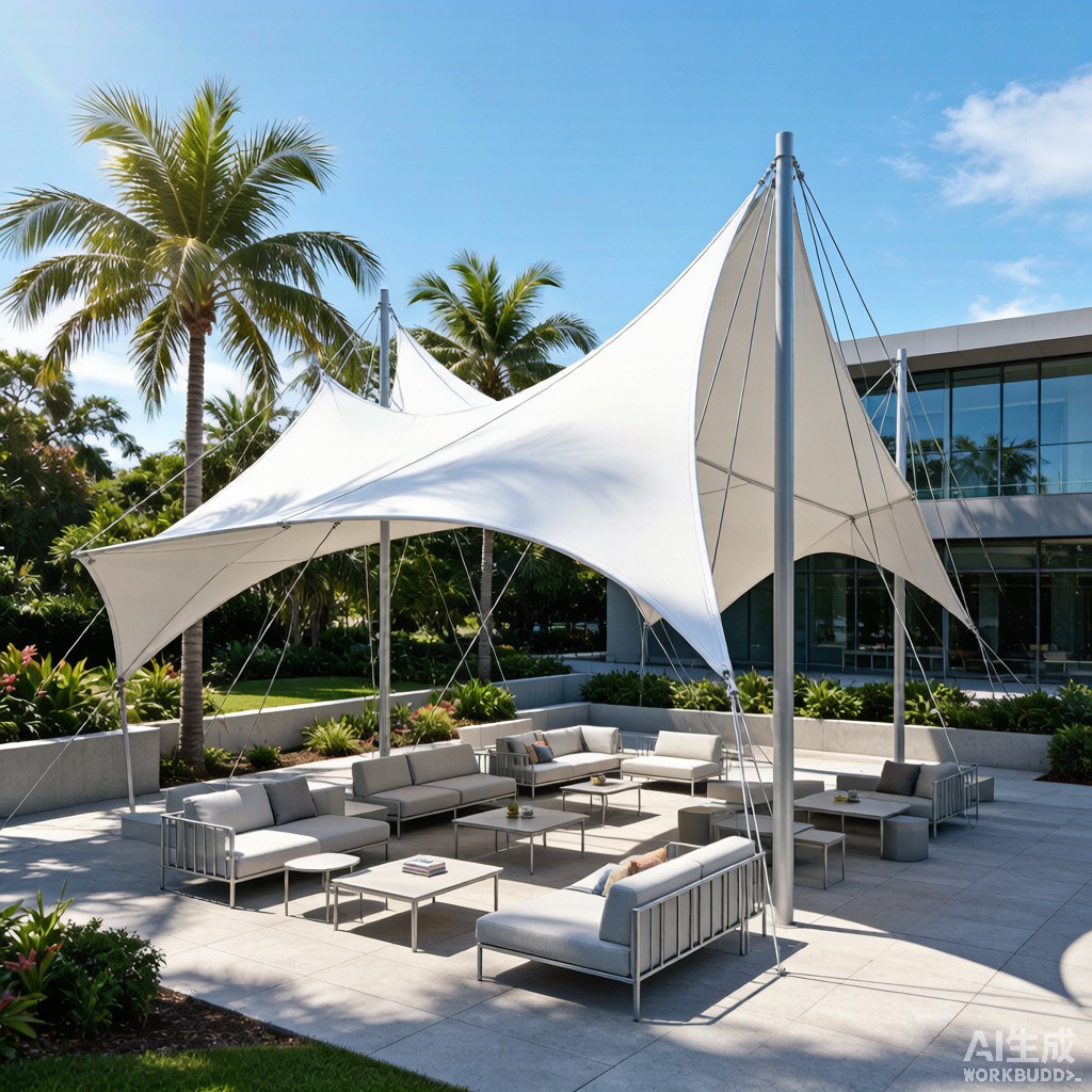
Introduction: Shade as Infrastructure
In tropical Southeast Asia, shade is not a luxury — it is the fundamental prerequisite for outdoor space usability. At solar noon in Bangkok, Singapore, or Jakarta, unshaded surfaces reach 50–65°C, and UV indices routinely exceed 11 (extreme). Tensile membrane shade canopies have emerged as the preferred architectural solution for outdoor lounge areas in public parks, commercial plazas, resort landscapes, and transit waiting zones because they combine efficient solar protection with dramatic visual presence at a lower structural cost than rigid roof systems.
However, these lightweight structures face a dual environmental challenge unique to tropical climates: typhoon-grade wind loads that create uplift forces exceeding the canopy’s dead weight, and intense UV radiation combined with fungal growth that degrades the membrane fabric. This article examines the engineering principles behind successful tensile membrane shade canopy design for tropical outdoor lounge applications.
Membrane Fabric Selection
PTFE vs PVC vs ETFE: The Material Decision
| Property | PTFE-Coated Fiberglass | PVC-Coated Polyester (Type II-IV) | ETFE Foil (single layer) |
|---|---|---|---|
| Base fabric | E-glass fiber, 3–6 μm diameter | High-tenacity polyester (PET), 1,100–1,670 dtex | None (homogeneous fluoropolymer film) |
| Coating / Film | PTFE (polytetrafluoroethylene), 70–90% of total weight | PVC (polyvinyl chloride) + PVDF or PVF topcoat | ETFE (ethylene tetrafluoroethylene), 100–300 μm |
| Tensile strength (warp/fill, kN/m) | 40–160 / 40–140 | 30–120 / 30–100 | 40–60 (isotropic) |
| Tear strength (N) | 300–1,200 | 300–900 | 200–450 |
| Design life (tropical climate) | 25–35 years | 12–18 years (PVDF topcoat); 15–22 years (PVF topcoat) | 20–30 years |
| Light transmission | 8–18% | 5–15% | 85–95% (clear); 50–60% (fritted) |
| Solar reflectance | 70–75% | 65–75% | 15–20% (clear); 50–60% (fritted) |
| UV resistance | Excellent (PTFE inherently UV-stable) | Good (PVDF/PVF topcoat protects PVC; topcoat degrades over time) | Excellent (ETFE inherently UV-stable) |
| Fungal resistance | Excellent (PTFE is inert; non-porous surface) | Moderate (PVC plasticizer supports fungal growth; requires biocide treatment) | Excellent (non-porous, inert) |
| Fire rating | Class A (ASTM E84); non-combustible | Class A with fire-retardant additives | Class A; self-extinguishing |
| Cost (USD/m², installed, 2026) | $250–500 | $80–200 | $300–600 |
| Self-cleaning | Excellent (PTFE surface energy ≈ 18 mN/m; hydrophobic) | Moderate (PVDF topcoat improves; TiO₂ self-cleaning available) | Excellent (ETFE surface energy ≈ 22 mN/m) |
For tropical outdoor lounge applications with a 15–25 year design life, the decision matrix typically narrows to:
- PTFE-coated fiberglass: Best long-term value despite higher initial cost. Its 25–35 year service life, excellent self-cleaning (maintaining high solar reflectance), and zero plasticizer migration make it the premium choice for permanent public installations.
- PVC-coated polyester with PVDF topcoat: The economic choice for projects with capital cost constraints. At 40–60% of PTFE’s installed cost, it achieves 12–18 year service life in tropical conditions — sufficient for developments with pla
ed renovation cycles. A
ual cleaning is required to prevent fungal staining, and the PVDF topcoat should be inspected for erosion every 3–5 years.
- ETFE foil: Best for applications requiring high light transmission (botanical garden lounge areas, covered walkways, greenhouse-style pavilions). Its transparency creates a different architectural aesthetic — more greenhouse than shade canopy — and the installed cost is comparable to PTFE.
Wind Load Analysis
The Wind Uplift Challenge
Tensile membrane canopies are lightweight structures. A typical PTFE canopy weighs 1.0–1.5 kg/m² (including fabric + cables + clamps), whereas the wind uplift pressure under typhoon conditions can exceed 1.5 kN/m² (150 kg/m²) — a net uplift force 100× the dead weight. Unlike rigid roofs that rely on dead load to resist uplift, membrane canopies must resist wind entirely through prestress tension and cable anchorage to the supporting structure.
Determining Design Wind Speed
| Location | Basic Wind Speed V (km/h) | Return Period | Standard | Exposure Category |
|---|---|---|---|---|
| Singapore | 115 | 50 years | EN 1991-1-4 (NA to SS) | Category II (urban) |
| Bangkok, Thailand | 108 | 50 years | DPT 1311-50 (based on ASCE 7) | Category II |
| Ho Chi Minh City, Vietnam | 140 | 50 years | TCVN 2737:1995 | Category I (open terrain) |
| Manila, Philippines | 250 (typhoon) | 50 years | NSCP 2015 (ASCE 7-based) | Category II |
| Jakarta, Indonesia | 100 | 50 years | SNI 1727:2013 (ASCE 7-based) | Category II |
The Philippines is the most demanding Southeast Asian wind environment for tensile membrane design, with basic wind speeds of 250 km/h (approximately 3.0 kPa velocity pressure at mean roof height). This is 2.3× the wind pressure in Singapore (115 km/h → 0.63 kPa velocity pressure) and represents a fundamentally different structural design challenge.
Pressure Coefficient Selection for Canopy Shapes
Unlike buildings with well-defined external pressure coefficients (Cp) in ASCE 7, tensile membrane canopies have continuously curved surfaces that produce complex pressure distributions. Key aerodynamic considerations:
| Canopy Form | Critical Wind Direction | Cp (net, worst case) | Behavior |
|---|---|---|---|
| Conic (tent/umbrella shape) | Any (axisymmetric) | -1.8 (uplift); +0.8 (downward) | Vortex shedding at leeward side; fabric flutter possible at 10–20 m/s if prestress insufficient |
| Hypar (hyperbolic paraboloid, saddle shape) | 45° to principal axes | -1.5 (uplift); +0.6 (downward) | Wind tu
els through the saddle; lowest net Cp; most aerodynamically stable form |
| Barrel vault (cylindrical) | Perpendicular to axis | -2.0 (uplift at windward edge); +0.5 (center) | Strong uplift at leading edge; separation bubble causes oscillating pressure |
| Free-form (NURBS surface) | Wind tu
el test required |
Determined by wind tu
el |
Ca
ot be predicted by code coefficients; CFD or wind tu el mandatory for final design |
The hyperbolic paraboloid (hypar) — formed by four points not in a plane, creating a saddle surface — is the preferred form for large outdoor lounge canopies because its double curvature provides both geometric stiffness and favorable wind aerodynamics. The concave curvature in one direction creates a pressure-recovery zone that reduces net uplift compared to purely convex forms.
Form-Finding and Prestress Design
The Equilibrium Shape Problem
Unlike conventional structures where shape precedes stress analysis, tensile membrane structures are form-found: the shape is the result of applying a specified prestress to a defined boundary. There is no unique shape for a given boundary — there is a family of equilibrium shapes, each corresponding to a different prestress ratio (warp-to-fill stress ratio, typically 1:1 to 2:1).
The design prestress values for outdoor lounge canopies:
| Parameter | PTFE | PVC/PES | ETFE |
|---|---|---|---|
| Minimum prestress (warp) | 2.0–3.0 kN/m | 1.5–2.5 kN/m | 1.0–2.0 kN/m |
| Maximum service stress | ≤ 8–10 kN/m (≈ 20% of tensile strength) | ≤ 6–8 kN/m (≈ 20% of tensile strength) | ≤ 8–12 kN/m (≈ 20–30% of tensile strength) |
| Target stress ratio (warp:fill) | 1:1 to 1.5:1 | 1:1 | 1:1 |
The minimum prestress must satisfy two conditions simultaneously:
- Zero stress criterion: Under the worst-case wind suction (uplift) load combination, no element of the membrane shall go slack (stress = 0). Slack membranes flutter violently, causing fatigue failure at seams and edge details within hours.
- Ponding criterion: For canopies with concave regions, the membrane must maintain positive Gaussian curvature under rain load to prevent water ponding, which adds static load and accelerates creep.
Cable and Co
ection Detailing
The boundary cable — typically galvanized or stainless steel wire rope (6 × 19 or 6 × 36 construction, IWRC) — transfers membrane prestress and wind loads to the supporting structural frame. Critical design parameters:
| Component | Specification | Notes |
|---|---|---|
| Boundary cable | SS 316L, Ø12–20 mm, 6 × 36 IWRC | 316L for coastal/chloride exposure; 304 acceptable inland |
| Cable prestress | 10–20% of MBL (minimum breaking load) | Compensates for construction stretch and thermal expansion |
| Membrane-to-cable clamp | Aluminum 6061-T6 extrusion with SS316 bolts | Continuous clamp preferred over point clamps for uniform stress transfer; continuous clamp reduces stress concentration by 40–60% |
| Mast base plate | Hot-dip galvanized steel or SS316, bolted to reinforced concrete foundation | Design for uplift + moment; mast base is the single point of failure for the entire canopy |
| Turnbuckle / tensioner | SS316, rated for 150% of maximum cable load | Allow ±50 mm adjustment for prestress application and re-tensioning |
For tropical outdoor lounges within 5 km of the coast, all steel components must be 316L stainless steel or hot-dip galvanized with minimum 85 μm zinc coating (ISO 1461). 304 stainless steel will develop tea staining and pitting corrosion within 2–5 years in coastal tropical environments — a cosmetic failure that erodes public confidence even if structural integrity is maintained.
Tropical Durability: UV, Fungi, and Cleaning
UV Degradation Mechanisms
Tropical UV radiation (integrated a
ual UV-A + UV-B ≈ 250–350 MJ/m²) is 30–50% higher than temperate latitudes, accelerating polymer degradation in membrane fabrics:
- PTFE/fiberglass: PTFE is inherently immune to UV degradation (C-F bond energy = 485 kJ/mol vs UV photon energy = 300–400 kJ/mol). The glass fibers are also UV-inert. PTFE membranes in Thailand and Singapore have been documented with less than 5% tensile strength loss after 20 years of exposure.
- PVC/PES with PVDF topcoat: The PVDF (polyvinylidene fluoride) topcoat is UV-resistant (C-F bonds similar to PTFE) but is applied as a thin lacquer (10–25 μm). After 8–12 years of tropical UV, the PVDF erodes to the point where the underlying PVC is exposed. PVC undergoes dehydrochlorination under UV, releasing HCl and causing chain scission that reduces tensile strength. A PVF (Tedlar) film laminate topcoat (25–50 μm) extends protection to 15–22 years but costs 30–50% more than PVDF lacquer.
Fungal Growth and Staining
In the warm, humid tropical environment (25–35°C, 80–95% RH, frequent rainfall), membrane surfaces support biofilm formation — a combination of algae, fungi, and bacteria that creates dark staining and, on PVC membranes, accelerates plasticizer degradation. Fungal staining on white/light-colored membranes is the most common aesthetic durability complaint in tropical installations.
Mitigation strategies:
- PTFE: The hydrophobic surface (contact angle > 110°) and chemical inertness prevent biofilm adhesion. Self-cleaning through rain is sufficient in most tropical locations. A
ual mild detergent washing maintains > 90% solar reflectance.
- PVC/PES: Biocide-treated topcoats (isothiazolinone or silver-ion based) suppress fungal growth for 3–5 years. After biocide depletion, quarterly pressure washing (max 5 MPa, fan nozzle at 45° angle, 0.5 m distance) with mild detergent is required to maintain appearance. Abrasive cleaning accelerates topcoat erosion — a difficult trade-off in locations where labor for gentle cleaning is not available.
Lifecycle Cost Comparison
| Cost Element | PTFE/Fiberglass | PVC/PES (PVDF topcoat) | ETFE Foil |
|---|---|---|---|
| Fabric material + fabrication (USD/m²) | $120–200 | $30–60 | $150–250 |
| Structural frame (steel, USD/m²) | $80–150 | $80–150 | $100–200 |
| Cables + co
ection hardware (USD/m²) |
$30–60 | $20–50 | $30–60 |
| Foundation (USD/m²) | $40–80 | $40–80 | $50–100 |
| Installation (USD/m²) | $30–50 | $20–40 | $40–60 |
| Installed cost (USD/m²) | $300–540 | $190–380 | $370–670 |
| Design life (tropical, years) | 25–35 | 12–18 | 20–30 |
| A
ual cleaning cost (USD/m²) |
$2–5 | $8–15 | $2–5 |
| A
ualized cost over 25 years (USD/m²/yr) |
$17–27 | $19–34 | $24–37 |
Despite its 60–90% higher initial cost, PTFE achieves the lowest 25-year a
ualized cost due to its longer service life and lower maintenance requirements. For developments with a 25+ year pla
ing horizon — public parks, transit hubs, institutional plazas — PTFE is the economically rational choice. For developments with a 10–15 year horizon or capital cost constraints, PVC/PES with PVDF topcoat is viable if a disciplined cleaning and inspection program is budgeted and executed.
Case Study Parameters: 100 m² Outdoor Lounge Canopy
For a typical 100 m² (10 m × 10 m coverage) hypar canopy at a tropical park in Singapore (V = 115 km/h, Exposure C):
| Design Parameter | Value | Notes |
|---|---|---|
| Plan area | 100 m² | Seats 30–40 lounge chairs |
| Fabric area (curved surface) | 115–130 m² | ~15–30% larger than plan area due to double curvature |
| Mast height | 4.5–6.0 m | High point; low points at 2.5–3.5 m |
| Design wind pressure (net uplift, Cp × qz) | 1.14 kPa (Cp = -1.8 × qz = 0.63 kPa at 5 m height) | Singapore basic wind speed 115 km/h → qz = 0.613 × V²/1,000 = 0.50 kPa at 10 m; adjusted for 5 m height |
| Total uplift force | 148 kN | Equivalent to lifting 15 to
es |
| Required cable MBL (4 corner cables, FS = 2.5) | 93 kN per cable | Ø16 mm SS316 6 × 36 IWRC (MBL = 205 kN; adequate) |
| Foundation uplift reaction (per mast) | 37 kN (design) × 2.0 FS = 74 kN | 1.2 × 1.2 × 0.8 m reinforced concrete footing, 80 kPa allowable bearing; OK |
Conclusion
Tensile membrane shade canopies represent the optimal marriage of structural efficiency, architectural expression, and climate-responsive design for tropical outdoor lounge environments. Their success hinges on three engineering decisions: fabric material selection (PTFE for permanence, PVC/PES for economy), wind-resistant form-finding (hypar geometry for aerodynamic stability), and corrosion-resistant co
ection detailing (316L stainless steel for coastal environments). In a region where solar radiation and typhoon winds define the outdoor experience, a well-engineered tensile membrane canopy transforms a hostile midday plaza into a comfortable, visually striking community space — a return on infrastructure investment measured not in dollars, but in hours of public use.



