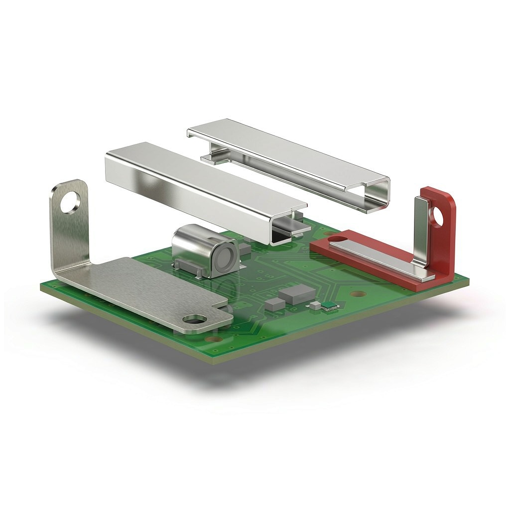
Board-level electromagnetic interference (EMI) shielding for SMT modules has traditionally been implemented with one-piece drawn metal cans soldered directly to the PCB ground plane. While effective, these cans create a maintenance barrier: removing them for rework or inspection damages the can and often the surrounding solder joints. Two-piece shielding systems — either clip-and-lid or frame-and-lid configurations — have become the dominant solution in smartphones, IoT gateways, automotive ECUs, and 5G small cells where post-reflow access to RF components is essential. This article compares SMT EMI shielding clips and frame-and-lid cans across assembly compatibility, shielding performance, rework, and total cost.
Shielding System Architectures
Clip-and-Lid vs Frame-and-Lid
Both two-piece systems separate the PCB-mounted ground member from the removable cover, but they differ in mechanical construction:
| Feature | Clip-and-Lid | Frame-and-Lid |
|---|---|---|
| Ground member | Small discrete clips (2-6 per shield) | Continuous frame soldered around perimeter |
| Lid attachment | Clips grip lid edges by spring force | Lid snaps or slides into frame rails |
| Typical height | 1.0-3.0 mm | 1.5-6.0 mm |
| Perimeter openings | Small gaps between clips | Continuous contact around full perimeter |
| Rework access | Remove lid, clips stay on board | Remove lid, frame stays on board |
| Best application | Small single IC shields (RF PA, PMIC) | Large multi-chip zones (modem, radar) |
Clip systems minimize ground-member footprint and allow denser shield placement in smartphone-size boards. Frame systems provide more uniform shielding around large zones and tolerate taller internal components such as co
ectors and film capacitors.
Reflow and Assembly Compatibility
Temperature and Co-Planarity
Both clips and frames must survive lead-free reflow peak temperatures of 245-260°C without losing spring force or solderability. Common materials include:
- C5210 phosphor bronze: Good spring properties, tin or nickel plating, cost-effective for low-profile clips.
- C17200 beryllium copper: Excellent fatigue resistance and high-temperature spring force; preferred for high-reliability applications.
- C19400 copper-iron: Balance of strength and stress relaxation for frames exposed to automotive underhood temperatures.
- Stainless steel 301: Highest corrosion resistance but requires active solderable plating (Sn or Ni-Sn).
Co-planarity of clip contact feet and frame rails must be controlled to within 0.05-0.10 mm to prevent solder opens during reflow. Tape-and-reel packaging with embossed pockets protects clip geometry during shipping and pick-and-place handling.
Shielding Effectiveness Comparison
SE at RF Frequencies
The shielding effectiveness of a two-piece system depends on lid material, seam geometry, and clip/frame contact density:
| Frequency Range | Clip-and-Lid SE | Frame-and-Lid SE | Dominant Leakage Path |
|---|---|---|---|
| 30-300 MHz | 40-60 dB | 50-70 dB | Perimeter slot resonance |
| 300 MHz-1 GHz | 35-55 dB | 45-65 dB | Clip spacing and lid fit |
| 1-6 GHz | 30-50 dB | 40-60 dB | Gap impedance at seams |
| 6-18 GHz | 25-40 dB | 35-50 dB | Lid surface finish and frame contact |
Frame-and-lid systems generally offer 5-15 dB higher shielding at all frequencies because the continuous frame perimeter eliminates the discrete clip spacing that creates slot ante
as. For 5G mmWave modules operating above 24 GHz, frame-and-lid with spring-finger sidewall contact is typically required.
Rework and Field Service
Non-Destructive Access
The primary advantage of two-piece shielding is non-destructive access to components beneath the lid:
- Clip lids: Removed with plastic pry tool or vacuum pick-up; clips remain soldered to PCB; lid can be reinstalled 5-20 times depending on clip design.
- Frame lids: Removed by sliding, snapping, or releasing latches; frame remains soldered; lids designed for 10-50 removal cycles.
- One-piece cans: Must be cut, drilled, or desoldered entirely; not reusable; risk of PCB pad damage.
For high-value RF modules requiring calibration after repair, clip-and-lid systems reduce rework cycle time by 50-70% and eliminate the consumable shield cost associated with one-piece cans.
Automation and Pick-and-Place
Feeding and Placement
Modern SMT lines handle both clips and frames as standard tape-and-reel components:
- Clip placement: 0402-to-0805 equivalent footprint; standard nozzles at 20,000-40,000 CPH; vision recognition of flat foot geometry.
- Frame placement: Larger custom trays or tape; often placed last after smaller components; requires larger nozzle and lower placement force to avoid distortion.
- Lid placement: Typically a secondary offline operation or final SMT stage; lids may be hand-loaded for low volume or robotically placed for high volume.
Clip systems have a clear automation advantage for very small shields because multiple clips fit into the same tape-and-reel handling infrastructure as passives. Frame systems require more specialized feeding but reduce component count by replacing 4-6 clips with a single perimeter frame.
Cost Analysis
Bill of Material and Assembly Cost
For a typical single-IC shield zone of 15×15 mm:
| Cost Element | One-Piece Can | Clip-and-Lid | Frame-and-Lid |
|---|---|---|---|
| Shield component cost | $0.03-0.08 | $0.04-0.10 (4 clips + lid) | $0.06-0.15 |
| Placement cost | $0.01-0.02 | $0.01-0.03 | $0.02-0.04 |
| Rework shield replacement | $0.03-0.08 each access | $0.00 (reusable) | $0.00 (reusable) |
| Yield loss from rework damage | 2-5% | <0.5% | <0.5% |
| Effective cost over product life | Higher for serviceable products | Lowest for small shields | Lowest for large zones |
For consumer electronics with no expected field repair, one-piece cans remain the lowest first-cost option. For automotive, medical, telecom, and industrial products where rework and diagnostic access are required, two-piece clip or frame systems pay back within the first service event.
Selection Guidelines
Choose clip-and-lid EMI shielding for small single-chip zones below 25×25 mm, high-density smartphone boards, and applications with frequent RF calibration access. Choose frame-and-lid for large multi-chip modules, tall components, 5G mmWave shields above 6 GHz, and applications requiring the highest shielding effectiveness. One-piece soldered cans remain suitable for disposable consumer products where cost dominates and rework is not anticipated. The decision between clip and frame is ultimately a trade-off between footprint density, shielding performance, and serviceability requirements.



