Introduction
In high-speed SMT stamping operations, copper strip flatness and camber are often overlooked until they cause feeder jams, die misalignment, or dimensional drift in finished lead frames and co
ector contacts. These geometric defects originate in the slitting, a
ealing, and handling of copper strip, and they propagate directly into assembly yield losses. This article explains the mechanisms behind flatness and camber defects, how to measure them, and how to control them in a precision manufacturing environment.
Defining Flatness and Camber
Flatness describes the deviation of a strip surface from a perfect plane, measured as the maximum gap between the strip and a reference surface when the strip is placed under its own weight. For thin copper strip used in SMT lead frames, flatness is typically specified in millimeters per meter or as a maximum allowable height difference across a given length.
Camber refers to the longitudinal curvature of the strip edge — a side-to-side deviation along the length of the strip. It is usually expressed as the maximum lateral displacement of the free edge relative to a straight reference line. Excessive camber causes the strip to wander in automatic feeders, leading to mis-punched features and premature tool wear.
Typical Specification Ranges
| Parameter | Premium Grade | Standard Grade |
|---|---|---|
| Flatness | ≤ 2 mm/m | ≤ 5 mm/m |
| Camber | ≤ 2 mm/m | ≤ 5 mm/m |
| Strip Thickness Range | 0.10 – 0.30 mm | 0.30 – 0.80 mm |
| Application | Fine-pitch lead frames | General co
ectors |
Root Causes of Flatness and Camber Defects
Copper strip geometry is established during rolling, slitting, and a
ealing. Non-uniform reduction in the rolling mill creates internal stress gradients that manifest as coil set or crossbow. When the strip is slit from a wider master coil, residual stresses are released asymmetrically, causing camber and twist along the narrower strip.
A
ealing conditions also play a major role. Rapid heating or non-uniform furnace temperature distribution can lead to differential recrystallization, where one side of the strip softens more than the other. This difference in mechanical properties causes the strip to bow during cooling. Similarly, improper tension during winding or inadequate interleaf paper can create localized flattening or edge deformation.
Measurement Methods
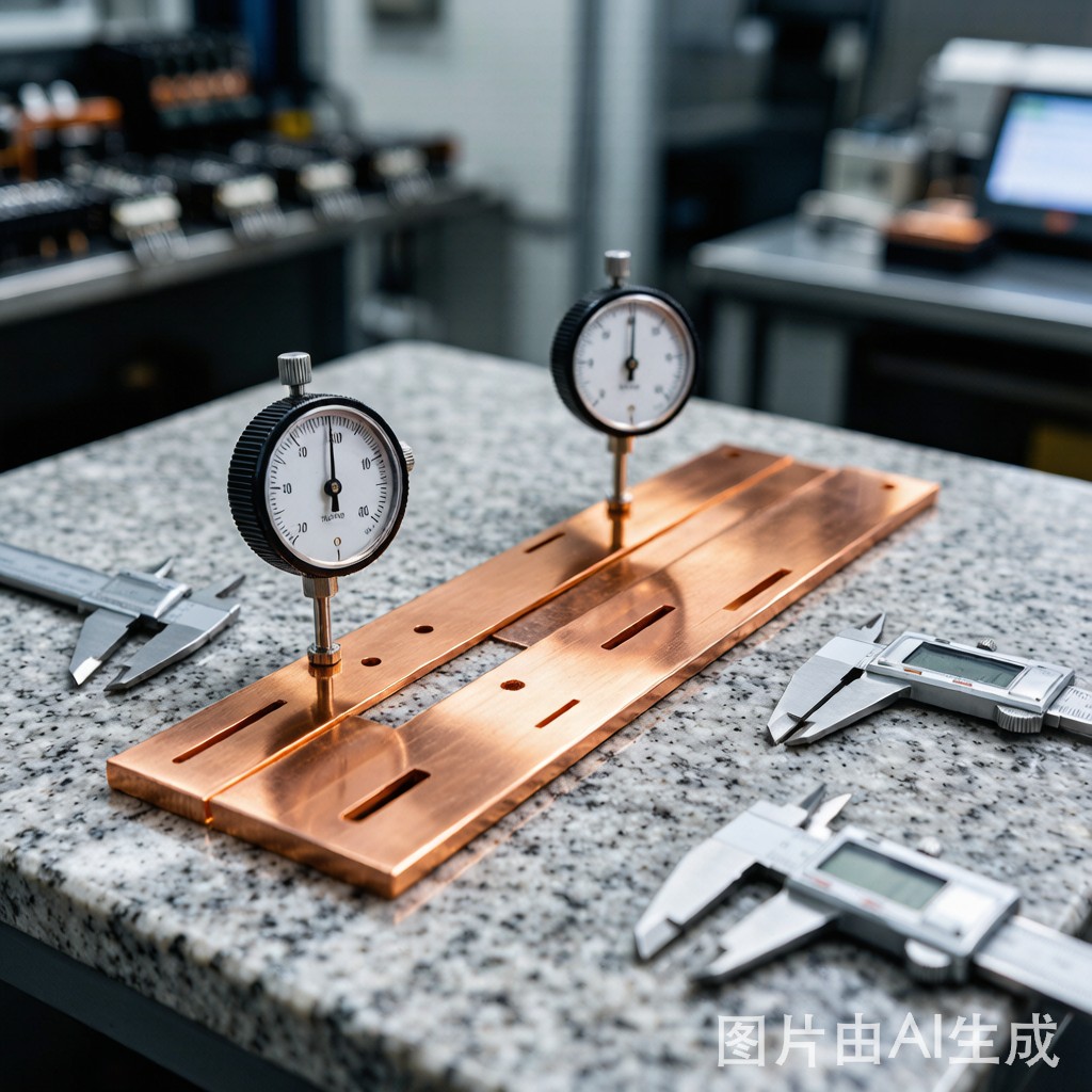
Flatness is commonly measured on a calibrated granite surface plate. The strip is placed concave-side down and the maximum gap between the strip and the plate is measured with feeler gauges or a dial indicator. For high-volume production, automated laser profilometers can scan the full width of the strip as it unwinds from the coil, providing continuous data and early warning of drift.
Camber measurement requires laying the strip on a flat surface and measuring the maximum deviation of the free edge from a straight line drawn between two fixed points. ASTM A568 and EN 1654 provide standard test methods for measuring edge camber in strip products. Digital imaging systems are increasingly used to capture camber profiles in real time during slitting.
Process Control Strategies
Controlling flatness and camber begins with uniform rolling practice. Symmetrical mill setups, consistent roll force distribution, and proper roll crown profiles reduce residual stress gradients. For critical applications, tension leveling or stretcher leveling can correct residual curvature by applying controlled plastic deformation across the strip width.
Slitting operations should use sharp, properly maintained knives with minimal clearance to avoid edge distortion and burr formation. Slitting in multiple passes or using tension-controlled recoiling helps minimize stress release. Finally, consistent a
ealing profiles with slow, uniform heating and cooling cycles are essential for maintaining geometric stability.
Impact on SMT Stamping and Assembly
Poor flatness reduces the effectiveness of vacuum or mechanical grippers in stamping presses, causing inconsistent feeding and pitch errors. Camber forces the strip against feeder guides, increasing friction and generating particles that contaminate dies and diesets. Over time, these issues reduce tool life, increase scrap rates, and compromise the dimensional accuracy of SMT lead frames and contacts.
Conclusion
Copper strip flatness and camber are not merely cosmetic attributes — they are critical process parameters that determine the efficiency and yield of high-speed SMT stamping. By measuring these properties against established standards, identifying root causes in rolling and slitting, and applying tension leveling or process corrections, manufacturers can maintain the geometric precision required for today’s fine-pitch electronic components.



