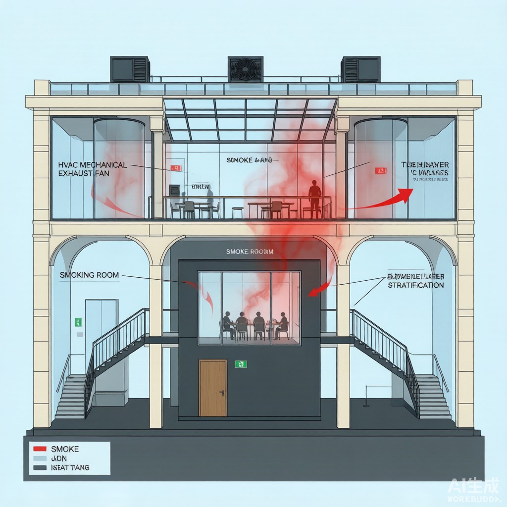
Introduction: The Smoke Challenge That HVAC Can’t Solve Alone
When a commercial smoking room is integrated into a multi-story building with an open atrium — increasingly common in Southeast Asian mixed-use developments, transit hubs, and office complexes — the fire safety design must address a scenario that standard HVAC design does not: a fire within or adjacent to the smoking room generating smoke that migrates into the atrium, compromising the means of egress for occupants on upper floors.
While standard smoking room ventilation systems manage tobacco smoke under normal conditions (see our article on smoking booth HVAC cooling load calculation), NFPA 92 — Standard for Smoke Control Systems — provides the engineering framework for managing fire smoke through active mechanical systems. This article examines the application of NFPA 92 to smoking room-atrium configurations, covering smoke layer calculation, exhaust sizing, make-up air design, and tenable environment verification.
NFPA 92 Smoke Control Methods
Method Selection
NFPA 92 recognizes two primary smoke control methods for atria and large spaces:
| Method | Description | Applicability to Smoking Room-Atrium | Key Design Parameter |
|---|---|---|---|
| Smoke exhaust (NFPA 92, Chapter 4) | Mechanically exhausts the smoke layer to maintain it above the highest occupied level. Make-up air supplied below the smoke layer. | Primary method for smoking room fire scenario where smoke enters atrium | Smoke layer height (z) ≥ 1.83 m above highest walking surface |
| Opposed airflow (NFPA 92, Chapter 5) | Creates air velocity through openings that opposes smoke movement. | Secondary method; used to prevent smoke migration from smoking room into atrium at the doorway | Minimum air velocity 0.75 m/s through doorway opening |
| Pressurization (NFPA 92, Chapter 6) | Maintains pressure differential across barriers to contain smoke to the fire zone. | Applicable to stairwells and elevator shafts adjacent to atrium | Minimum ΔP = 12.5 Pa (closed doors); force to open door ≤ 133 N |
For the smoking room-atrium configuration, a hybrid approach is most effective: opposed airflow at the smoking room door (to contain smoke within the room of origin) combined with smoke exhaust in the atrium (as the secondary defense if smoke breaches the doorway).
Design Fire Scenario and Smoke Production
Fire Size Determination
The design fire for a commercial smoking room must consider combustible contents including upholstered seating, waste receptacles, and adjacent combustible materials. Per NFPA 92, the design fire may be steady-state (constant heat release rate, HRR) or time-dependent (t² growth fire).
For a typical 15–30 m² smoking room with 2–6 occupants:
| Design Parameter | Value | Rationale |
|---|---|---|
| Design fire HRR (steady-state) | 1.0–2.5 MW | NFPA 92 A
ex B; upholstered seating fire |
| Growth rate | Medium (t², α = 0.0117 kW/s²) | Upholstered furniture + waste receptacle |
| Time to reach design HRR | 292–460 seconds | t = √(Q/α) for 1.0–2.5 MW |
| Fire perimeter (P_f) | 3–6 m | Assumes localized fire, not fully involved room |
| Smoke layer interface (clear height in room) | 1.5 m above floor | Tenability threshold per NFPA 92 |
Axisymmetric Plume Smoke Production
For a fire in the smoking room that vents smoke into the atrium (e.g., through an open door or failed fire-rated glazing), the smoke mass flow rate entering the atrium is calculated using the axisymmetric plume equation from NFPA 92:
m = 0.071 · Q_c^(1/3) · z^(5/3) + 0.0018 · Q_c
Where m = smoke mass flow rate (kg/s), Q_c = convective HRR (≈ 0.7 · Q_total, kW), z = height from fire base to smoke layer interface (m).
For Q = 2.0 MW (Q_c = 1,400 kW) and z = 2.2 m (floor to atrium ceiling smoke layer):
m = 0.071 × 1,400^(1/3) × 2.2^(5/3) + 0.0018 × 1,400 = 8.4 kg/s
This high smoke production rate — 8.4 kg/s (≈ 25,200 m³/h at smoke temperature) — demonstrates why passive smoke management in atria is rarely feasible and why mechanical smoke exhaust systems must be sized generously.
Mechanical Smoke Exhaust System Design
Exhaust Rate Calculation
The required volumetric exhaust rate (V_exhaust) at the smoke layer temperature is:
V_exhaust = m / ρ_smoke
Where ρ_smoke = smoke density at the smoke layer temperature (typically 40–80°C, ρ ≈ 1.0–1.12 kg/m³ — slightly lower than ambient air at 1.2 kg/m³ due to thermal expansion).
| Parameter | Value | Notes |
|---|---|---|
| Smoke mass flow rate (m) | 8.4 kg/s | From axisymmetric plume equation |
| Smoke layer temperature | 60°C | Typical after dilution in atrium volume |
| Smoke density (ρ) | 1.06 kg/m³ | At 60°C |
| Required exhaust volume (V) | 7.92 m³/s = 28,512 m³/h | At smoke layer temperature |
| Safety factor (×1.3 per NFPA 92) | 37,066 m³/h | Accounts for plume wander, stratification |
Exhaust Fan Specifications
| Specification | Requirement | Standard |
|---|---|---|
| Temperature rating | 250°C for 2 hours (F300 classification) | EN 12101-3 |
| Motor location | Out of airstream (belt-drive, motor external) | NFPA 92 |
| Redundancy | N+1 fans; each ≥ 50% of total required capacity | NFPA 92 Section 4.4.5 |
| Fan type | Centrifugal or axial with high-temperature certification | NFPA 92 |
| Exhaust points | Minimum one per 1,000 m² atrium floor area, spaced ≤ 30 m | NFPA 92 |
Make-Up Air Design
Make-up air is as critical as exhaust — inadequate make-up air creates negative pressure that prevents the exhaust system from operating at its design flow rate. Key design rules:
- Make-up air velocity ≤ 1.0 m/s (to avoid disturbing the smoke layer).
- Make-up air inlet must be ≤ 1.5 m above floor level, below the smoke layer interface.
- Make-up air volume = 85–95% of exhaust volume (to maintain slight negative pressure in the smoke zone).
- For natural make-up air (louvers/doors that open automatically on fire alarm), the free area must be sized for 1.0 m/s maximum velocity.
Smoke Layer Stability and Stratification
Preventing Plume Penetration
A critical failure mode in atrium smoke control is plume penetration — when the fire plume’s upward momentum carries smoke through the design smoke layer and into the upper atrium, contaminating the clear layer below. The condition for the smoke layer to capture the plume is:
m_exhaust ≥ m_plume(at z = smoke layer height)
If the exhaust rate at the smoke layer interface is insufficient to capture the entire plume mass flow, the excess smoke rises above the layer — a condition called “plug-holing” — and renders the smoke control system ineffective for upper floors. This is why the 1.3× safety factor in NFPA 92 is not generous — it is the minimum required to account for real-world plume instability.
Stratification Check
In tropical Southeast Asian atria, the temperature gradient between the atrium interior (often air-conditioned to 26°C) and the outdoor environment (35°C+) creates a warm air layer near the atrium ceiling even without a fire. This thermal stratification can trap a smoke layer 1–2 m below the ceiling, reducing the effective smoke reservoir depth. The design smoke layer height (z) in NFPA 92 calculations must account for this pre-existing stratification by adding the measured ΔT between the smoke reservoir and ambient as a reduction factor to the plume buoyancy.
Interaction with Sprinkler Systems
Sprinkler-Smoke Interaction
In buildings equipped with automatic sprinklers, the water spray interacts with the smoke layer in three ways:
- Smoke cooling: Water droplets absorb heat from the smoke, reducing buoyancy and causing the smoke layer to descend. This can bring the smoke layer below the design height — a dangerous outcome that must be modeled.
- Smoke downdrag: The downward momentum of sprinkler spray droplets drags smoke from the layer into the clear zone below, reducing visibility and tenability below the design smoke interface.
- Reduced smoke production: Sprinklers reduce the fire HRR (and therefore smoke production) by wetting and cooling the fuel. The reduced HRR must be accounted for in the smoke exhaust design — NFPA 92 allows a reduction in design HRR when a properly designed sprinkler system is present, but this reduction varies by occupancy type.
For a smoking room-atrium configuration with a quick-response sprinkler system, the effective convective HRR for smoke exhaust design may be reduced to 0.5–1.0 MW (from the unsprinkled 1.4 MW), reducing smoke production by 50–65% and proportionally reducing the required exhaust capacity.
Opposed Airflow at Smoking Room Door
Design Parameters
As a first line of defense, the smoking room itself should be equipped with an opposed airflow system that prevents smoke migration into the atrium. Per NFPA 92 Section 5.6, the minimum air velocity through the open doorway is:
v_min = 0.75 m/s (for 1,000°C smoke temperature)
v_min = 0.64 m/s (for the reduced temperature of diluted smoke at the doorway)
For a standard 0.9 m (W) × 2.1 m (H) doorway, the required opposed airflow is:
V_opposed = v_min × A_door = 0.64 m/s × (0.9 × 2.1) m² = 1.21 m³/s = 4,356 m³/h
This airflow can be provided by the smoking room’s general exhaust system (normally sized for tobacco smoke at 600–1,200 m³/h), supplemented by a dedicated fire-mode exhaust fan that activates on smoke detection. The combined system must provide the full 4,356 m³/h at the door plane within 60 seconds of detection.
Tenable Environment Verification
NFPA 92 requires that the smoke control system maintain tenable conditions in the egress path for the time required for full building evacuation. Tenability criteria include:
| Parameter | Tenability Limit | Measurement Method |
|---|---|---|
| Smoke layer height | ≥ 1.83 m above walking surface | Beam detectors or visual observation |
| Temperature (smoke layer) | ≤ 200°C (maximum); ≤ 60°C (prolonged exposure) | Thermocouple tree in atrium |
| Visibility (clear layer) | ≥ 10 m (light-reflecting); ≥ 30 m (light-emitting signs) | Optical density meter (OD ≤ 0.1/m) |
| CO concentration | ≤ 1,500 ppm (5-min exposure); ≤ 500 ppm (30-min) | Gas analyzer |
| CO₂ concentration | ≤ 5% (acute); ≤ 3% (30-min) | Gas analyzer |
| O₂ concentration | ≥ 15% (minimum) | Gas analyzer |
System Integration and Commissioning
The smoke control system must integrate with the building fire alarm system through a dedicated smoke control panel that executes the following sequence on fire detection:
- Smoke detector activation in smoking room → signal to smoke control panel
- Smoke control panel commands: smoking room exhaust to fire mode (full opposed airflow), atrium smoke exhaust fans start, make-up air dampers open, all HVAC air handling units serving atrium zone shut down, stairwell pressurization fans activate
- Fire alarm system activates occupant notification throughout building
- Smoke control panel monitors: fan status (ru
ing/fault), damper position (open/closed), pressure differentials at stairwells, smoke layer depth via beam detectors
- Sequenced shutdown: sprinkler water flow stops → smoke purged → atrium fans run for minimum 30 min post-fire → manual reset
Commissioning must verify the full sequence under controlled test conditions, including smoke layer development (using cold smoke generators), fan performance (measured airflow at exhaust inlets and make-up openings), and pressure differentials at protected openings. NFPA 92 requires re-commissioning a
ually for the life of the building.
Conclusion
Integrating a commercial smoking room into a multi-story atrium building requires a smoke control design that goes far beyond the standard HVAC specification. NFPA 92 provides the engineering framework — axisymmetric plume equations, smoke layer stability criteria, and exhaust sizing methodology — to design a system that protects the means of egress for all building occupants. The opposed airflow method at the smoking room door provides the primary containment, while properly-sized atrium smoke exhaust serves as the critical secondary defense. For facility engineers and architects designing smoking rooms in Southeast Asian mixed-use developments, investing in compliant smoke control design is not a regulatory checkbox — it is the fundamental guarantee of life safety for building occupants above, beside, and below the smoking facility.



