## Introduction
The fundamental engineering principle of a smoking booth is simple: maintain the interior at a lower pressure than the surrounding space so that smoke ca
ot escape through gaps around the door. In practice, achieving reliable negative pressure — and maintaining it under varying occupancy, wind, and door-open conditions — requires careful attention to airflow distribution, capture hood geometry, and pressure differential monitoring.
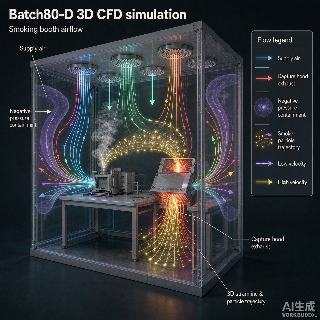
This article examines how computational fluid dynamics (CFD) analysis can be used to optimize smoking booth airflow, ensuring that negative pressure is maintained at the door gap while providing adequate ventilation for occupants.
## Negative Pressure Fundamentals
### Pressure Differential Targets
Building codes and guidelines for smoking enclosures typically specify a negative pressure differential of 5 Pascals (0.02 inches water gauge) relative to adjacent spaces. This value is based on the pressure needed to overcome buoyancy-driven flow from temperature differences (2–3 Pa for a 5-degree C interior-exterior temperature difference) plus a safety margin.
For smoking booths in public buildings, Singapore’s National Environment Agency (NEA) guidelines and UK Health Act 2006 Schedule 1 both reference 5 Pa as the minimum. Some jurisdictions recommend 7–10 Pa for added safety, particularly in buildings with strong stack effects or pressurized HVAC systems in adjacent spaces.
### Air Change Rate
The air change rate (ACH) determines how quickly smoke is removed from the booth. The recommended range for smoking enclosures is 30–60 ACH, with 40 ACH being a common design point. For a 6 square meter booth with 2.5 meter ceiling height (15 cubic meters), 40 ACH requires 600 cubic meters per hour (0.167 m3/s) of exhaust air.
The supply air volume should be 85–90% of the exhaust volume, with the remaining 10–15% drawn through the door gap and leakage paths. This imbalance creates the negative pressure differential.
## CFD Modeling Approach
### Geometry and Mesh
A representative CFD model of a smoking booth includes:
– The booth interior (typically 2 m x 3 m x 2.5 m).
– A ceiling-mounted supply air diffuser.
– A ceiling-mounted capture hood or exhaust grille.
– A door with a 5 mm bottom gap and perimeter weather stripping.
– The adjacent corridor space to capture door-gap leakage flow.
The mesh should use hexahedral elements in the interior with prism layers on walls to resolve boundary layer flow. Total cell count of 2–5 million provides adequate resolution for steady-state RANS (Reynolds-averaged Navier-Stokes) simulations.
### Boundary Conditions
– Supply diffuser: mass flow inlet corresponding to the design ACH.
– Exhaust grille: mass flow outlet set at 110–115% of supply.
– Door gap: pressure outlet co
ected to the corridor at atmospheric pressure.
– Walls: no-slip, adiabatic.
– Turbulence model: k-omega SST (suitable for low-Reynolds internal flows with separation).
### Smoke Particle Tracking
Smoke particles are modeled using Lagrangian particle tracking, with particle diameters of 0.1–1.0 micrometer (representing mainstream and sidestream smoke). Particle residence time (the duration particles remain in the booth) should be less than 60 seconds for acceptable air quality.
## Key Design Findings from CFD Analysis
### Capture Hood Placement and Geometry
The single most critical design parameter is the capture hood position relative to the smoking occupant. CFD analysis consistently shows that a ceiling-mounted exhaust grille located directly above the seating position provides the best capture efficiency. When the exhaust is placed on a side wall, capture efficiency drops by 30–40% because smoke plume momentum carries particles past the grille before they reach the capture zone.
The capture hood should have a minimum face area of 0.15 square meters and a face velocity of 1.5–2.5 m/s. Velocities above 3.0 m/s create draft complaints from occupants; velocities below 1.0 m/s result in poor capture of the buoyant smoke plume.
### Supply Air Distribution
Supply air should be introduced through a perforated ceiling or linear diffuser at the opposite end of the booth from the capture hood. This creates a plug-flow displacement pattern where clean supply air flows across the booth toward the exhaust, sweeping smoke with it. The supply velocity should be 0.3–0.5 m/s at the diffuser face to avoid creating turbulent mixing that would resuspend captured smoke.
A common error is using a high-velocity supply jet that induces mixing rather than displacement. CFD analysis shows that supply velocities above 1.0 m/s increase smoke residence time by 50–80% compared to displacement flow at 0.4 m/s.
### Door Gap Leakage Flow
The 5 Pa pressure differential drives an inward airflow through the door gap of approximately 15–25 cubic meters per hour for a standard 0.9 m wide door with a 5 mm bottom gap. This flow is sufficient to prevent smoke escape during normal operation. However, when the door is opened, the pressure differential temporarily collapses and smoke can escape for 5–10 seconds until the exhaust system re-establishes negative pressure.
CFD analysis of door-opening transients shows that increasing the exhaust capacity by 20% for 30 seconds after door opening (an active pressure-boost mode triggered by a door switch) reduces smoke leakage by 80–90%.
### Short-Circuit Prevention
Short-circuiting occurs when supply air flows directly to the exhaust without mixing with the room air. CFD analysis identifies short-circuiting by examining the age-of-air distribution. When the supply diffuser and exhaust grille are both ceiling-mounted and close together, up to 40% of supply air can short-circuit. Placing the supply at the opposite end of the booth or using a displacement ventilation strategy reduces short-circuiting to under 10%.
## Pressure Differential Monitoring and Control
### Differential Pressure Sensor
A differential pressure transducer with a range of 0–25 Pa and accuracy of plus or minus 0.5 Pa should be installed across the booth door, with one port inside the booth and one in the corridor. The sensor output is used to modulate the exhaust fan variable frequency drive (VFD) to maintain 5 Pa negative pressure.
When the pressure differential drops below 3 Pa — indicating a door-open event or filter loading — the control system increases exhaust fan speed by 10–20% and triggers a visual alarm.
### Filter Loading Compensation
As the HEPA and carbon filters load with particulate and tars, their resistance increases, reducing exhaust airflow. The pressure sensor feedback loop compensates by increasing fan speed. When the filter resistance exceeds the fan curve’s maximum, a maintenance alarm is triggered. Typical filter life in a smoking booth is 3–6 months for the pre-filter, 6–12 months for the HEPA, and 3–4 months for the carbon adsorption filter.
## Conclusion
Achieving reliable negative pressure in a smoking booth is not simply a matter of sizing an exhaust fan. The airflow distribution — driven by capture hood placement, supply air strategy, and door gap management — determines whether the booth actually contains smoke or merely achieves a pressure reading on a sensor. CFD analysis provides the quantitative insight needed to avoid common design failures such as short-circuiting, turbulent mixing, and inadequate door-gap leakage control. For smoking booth installations in public buildings across Southeast Asia, where ambient temperatures and humidity are high, a CFD-validated design ensures both regulatory compliance and occupant comfort.



