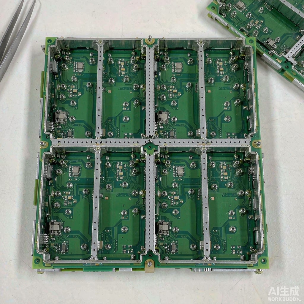
Why a Single Can Stops Working
The first-generation design puts one shield can over the whole RF section and calls it done. It passes radiated emissions at the lab and then fails in the field, because a single can shields the board from the outside world but does nothing to stop the 2.4 GHz power amplifier from desensitizing the GNSS front end sitting 15 mm away inside the same can.
The fix is partition: a fence of thin metal walls soldered to the board, dividing the can into cavities, with a lid that contacts the fence tops. Done well, adjacent-cavity isolation of 40 to 60 dB is achievable. Done carelessly, you get 15 dB and a new set of resonance problems you did not have before.
Anatomy of a Fence-and-Lid System
Fence material and thickness
Nickel silver (Cu-Ni-Zn, typically C7701) at 0.15 to 0.25 mm is the default for laser-cut or etched fences because it solders well, resists oxidation, and holds dimensional tolerance after forming. Tin-plated steel at 0.2 mm is cheaper and mechanically stiffer but heavier and more prone to whisker risk at cut edges. Brass is formable but its zinc content makes it marginal near flux residues.
At 2.4 GHz the skin depth in nickel silver is around 2.5 µm, so even 0.1 mm of wall is electrically thick. Material choice is therefore driven by solderability, flatness, and cost, not by shielding effectiveness.
Wall height and self-alignment
Fence height is set by the tallest component in the cavity plus clearance for the lid to sit flat. Typical values are 1.5 to 3.0 mm. Above 4 mm, the fence becomes unstable during reflow and tends to lean; specify a carrier or a folded flange foot.
Foot width matters more than most drawings suggest. A foot of 0.5 mm gives enough solder fillet to survive board flex; 0.3 mm feet crack at the toe after thermal cycling.
Lid attachment
Three options: a removable lid with dimples that snap into fence slots (serviceable, 30 to 40 dB), a soldered lid (best isolation, not reworkable without hot air), and a conductive gasket between lid and fence (compromise, degrades with compression set). For products that need RF tuning after assembly, specify the snap lid and accept the isolation penalty.
Cavity Resonance: The Constraint Everyone Forgets
A shield cavity is a rectangular waveguide with a closed top. It resonates at frequencies given by:
fmnp = (c/2) × √[(m/a)² + (n/b)² + (p/h)²]
where a and b are the cavity dimensions and h is the height. For a 30 × 20 mm cavity, the first mode lands near 9 GHz. Shrink it to a 30 × 30 mm square and the first mode drops to about 7 GHz. Push either dimension out to 60 mm and you have a resonance at 3.5 GHz, right on top of your Wi-Fi band.
The practical rule: keep every cavity dimension below about 35 mm if you need the first resonance above 6 GHz. If the layout forces a large cavity, three mitigations exist.
Absorber loading
A 0.1 to 0.5 mm magnetic absorber sheet on the lid interior damps cavity modes by 10 to 20 dB at 1 to 6 GHz. It costs money and Z-height, and the adhesive must survive reflow if applied before assembly.
Lossy coating
Carbon-loaded paint on the lid interior is cheaper than absorber but less effective below 2 GHz, and it complicates grounding if it bridges a fence contact area.
Deliberate segmentation
Add an internal fence wall that cuts the long dimension. A 60 × 30 mm cavity splits into two 30 × 30 mm cavities, each with its resonance pushed up an octave. This is almost always the cheapest fix and should be decided at layout, not after the first EMC failure.
Seam and Ground Stitching Design
Shielding effectiveness of a metal enclosure is limited by its apertures, not its walls. A seam gap behaves as a slot ante
a, and a slot radiates efficiently once its length approaches a half wavelength.
The λ/20 rule
Keep the longest unbroken gap below one-twentieth of a wavelength at the highest frequency of concern. At 2.4 GHz, λ is 125 mm, so gaps must stay under 6 mm. At 6 GHz, λ is 50 mm and the limit is 2.5 mm. At 10 GHz it is 1.5 mm, which is why mmWave designs need continuous soldered seams rather than dimpled lids.
Via stitching under the fence
The fence sits on a ground pad, and that pad must co
ect to the internal ground plane through vias. Use the same λ/20 criterion for via pitch, then apply a manufacturing margin: 2 to 3 mm pitch at 2.4 GHz, 1.5 mm at 5 GHz. A fence soldered to a pad with no vias is a floating wall and contributes almost nothing.
Place the via row directly under the fence wall, not offset to one side. An offset of more than 0.5 mm creates a parallel-plate resonance between the pad and the plane beneath.
What Isolation Number Should You Target
Isolation requirements come from the receiver, not from the shield. Work backwards:
- GNSS front end: signal at −130 dBm, cellular transmit at +23 dBm. Even with a SAW filter ahead of the LNA, you typically need 60 to 80 dB of board-level isolation and physical separation.
- Wi-Fi and Bluetooth coexistence: 25 to 35 dB of ante
a-to-ante
a isolation is usually sufficient because the radios time-share, but only if the ante
as are cross-polarized.
- Switching regulator to sensitive analog: 20 to 30 dB is often enough if the harmonics are already filtered at the source.
Measure isolation with a two-port VNA using small coax pigtails soldered temporarily into each cavity. Perform this before the enclosure is finalized, while you can still move a fence.
Manufacturing and Rework Realities
- Keep-out for pick-and-place. Fences need 0.5 mm clearance for nozzle access; components placed closer will be damaged during fence installation.
- Fence flatness. Anything over 0.05 mm warp lifts the foot off the pad and creates both a solder void and a seam gap.
- Solder volume. Fence feet wick a surprising amount of paste. Add 20 to 30% paste area on fence pads or you will see skip soldering at the corners.
- Rework access. If a component inside a cavity is likely to fail, design a lid with a localized cut-out rather than pla
ing to desolder an entire lid.
- Thermal mass. A large fence pulls heat from adjacent joints during reflow. Extend the soak zone by 10 to 15 seconds for boards with full-perimeter fences.
Design Review Checklist
- Is every cavity dimension below 35 mm, or is there an absorber or segmentation plan?
- Does each fence foot sit on a solid ground pad with vias at λ/20 pitch directly beneath the wall?
- Are all seam gaps under 6 mm at 2.4 GHz, or 2.5 mm at 5 GHz?
- Is there 0.5 mm placement clearance on both sides of every wall?
- Has isolation been measured on a first article, not assumed from simulation?
- Can the lid be removed without destroying the fence, and is that documented in the rework procedure?



