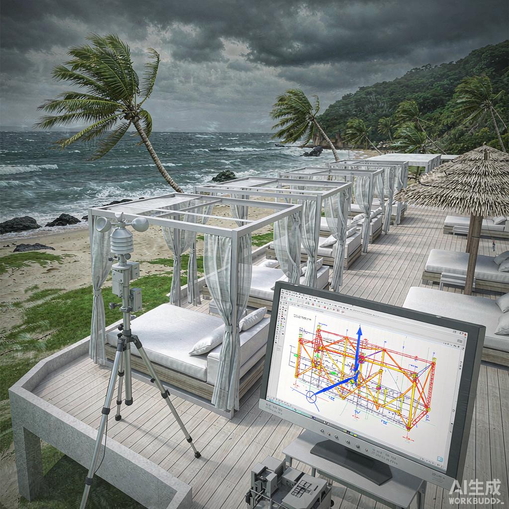
Why Wind Load Engineering Matters for Tropical Outdoor Lounges
Outdoor lounges in tropical resort destinations-from Phuket to Bali to Cebu-are routinely exposed to typhoon-strength winds, salt-laden air, and torrential rain. An inadequately designed aluminum-framed lounge structure can suffer panel blowout, anchor pull-out, or complete frame collapse at wind speeds below the building code minimum. The combination of high basic wind speed (45-65 m/s in cyclone zones), Exposure Category C or D coastal terrain, and large roof areas creates demand loads that surprise designers accustomed to inland, low-rise construction. This article covers the analytical framework for designing aluminum-framed outdoor lounges to withstand tropical cyclone events, from basic wind speed selection through anchor pull-out testing.
Basic Wind Speed and Exposure Category Selection
ASCE 7-22 and EN 1991-1-4 Mapping
The design starts with the basic wind speed V (3-second gust at 10 m height in open terrain) for the project location:
- ASCE 7-22 (US and Asia-Pacific projects following US practice): 3-second gust wind speed with Risk Category II. Map values range from 38 m/s (85 mph) in non-cyclone inland areas to over 70 m/s (155 mph) along the Gulf of Mexico, Bay of Bengal, and Western Pacific typhoon tracks.
- EN 1991-1-4 (European practice): 10-minute mean wind velocity vb,0 with directional and seasonal factors. Tropical cyclone regions show vb,0 of 30-45 m/s.
- Hong Kong Code of Practice on Wind Effects: 3-second gust at 10 m, with site-specific values typically 45-55 m/s and explicit allowance for typhoon windows.
For Southeast Asian resort projects, default to the higher of the local national code, ASCE 7-22 Risk Category III, and the insurer’s published wind speed map. Insurance carriers frequently demand higher reliability than the code minimum to maintain coverage.
Exposure Category C and D for Coastal Sites
Open-water and flat-grass coastal terrain falls under Exposure Category C (ASCE 7-22) or Category II (EN 1991). Direct shoreline sites with offshore wind fetch of more than 1 km fall into Exposure Category D. The exposure category multiplier changes the velocity pressure by up to 38% (q ∝ V²), so a site-specific decision matters.
| Site Type | Exposure Category | Velocity Pressure Multiplier vs B |
|---|---|---|
| Inland, suburban | B | 1.00 |
| Open grassland, scattered trees | C | 1.43 |
| Direct shoreline, offshore fetch >1 km | D | 1.85 |
Roof and Wall Pressure Coefficients
External Pressure Coefficients (Cp)
Aluminum-frame outdoor lounges are typically monoslope or hip-roof structures with partially open walls. ASCE 7-22 Figure 30.3 provides Cp values for these geometries:
- Roof zones: Interior zone (0.0 to -0.5), edge zone (-0.9 to -1.4), corner zone (-1.5 to -2.2). The corner uplift is the dominant design load for canopy and awning structures.
- Side walls (partially enclosed): Windward +0.8, leeward -0.3 to -0.5 depending on aspect ratio.
- Open walls (lounge front facing prevailing wind): +0.8 windward with +0.7 gust factor contribution.
For partially enclosed lounges, the internal pressure coefficient GCpi of ±0.55 amplifies roof uplift when wind enters the open front. Specify pressure-relief panels (≥10% of wall area) or sufficient ope
ess to qualify as an open structure under ASCE 7-22 §26.10. Otherwise, GCpi = ±0.55 must be applied.
Directional Procedure Required for Lounges
Because lounges have unusual aspect ratios (long and shallow, often 4:1 or 5:1) and partially open walls, the simplified envelope procedure in ASCE 7-22 §27 is not adequate. Use the directional procedure in §28 with a wind directionality factor Kd = 0.85 for roof uplift, 0.90 for frames, and 0.95 for corner panels. Apply the alongwind, acrosswind, and torsional components per §28.3 and check the 16 load combinations in §2.3.
Aluminum Frame Member Sizing
Section Selection and Alloy
Specify structural alloy 6061-T6 for primary beams and 6063-T5 for secondary members. Avoid 6005-T5 for major structural members in cyclone regions; it has lower ultimate strength. Common sections:
- Primary beam: 200x100x4 mm rectangular hollow section (RHS) or 250x75x3 mm RHS for spans 6-9 m.
- Secondary rafter: 150x50x3 mm RHS at 1.2-1.5 m spacing.
- Column: 150x150x5 mm SHS (square hollow section) with 10 mm base plate.
- Roof purlin: 100x50x2 mm RHS at 0.6-0.8 m spacing.
Use ASD or LRFD per ADM (Aluminum Design Manual) 2020 with safety factor 1.65 for yielding and 1.95 for rupture. For Southeast Asia, follow AAMA 2002 or AS/NZS 1664.1 for allowable stress design of aluminum structures. Check both flexural and lateral-torsional buckling for unbraced compression flanges.
Co
ections and Welds
All field co
ections should be mechanical (bolted) rather than field-welded. Use 10.9-grade hot-dip galvanized bolts with oversize holes filled against a compressible gasket. Fillet welds at factory should be full-strength weld (ER5356 or ER5183 filler for 6061-T6). Specify weld procedure qualification tests (WPQT) and 100% visual inspection plus 10% magnetic particle testing for cyclonic-zone structures.
Anchor Pull-Out and Base Plate Design
Concrete Anchor Selection
Base plate anchors typically use post-installed mechanical anchors (Hilti HIT-RE 500 V3, Powers Fasteners Power-Stud+ SD2) or cast-in headed studs. For cyclone regions:
- Anchor diameter: M16 minimum, M20 preferred for primary columns.
- Embedment depth: 10d minimum for cast-in, 12d for post-installed mechanical anchors.
- Edge distance: 12d from any concrete edge to prevent splitting failure.
- Concrete strength: 30 MPa minimum at 28 days; 40 MPa preferred.
Calculate tension demand from roof uplift (q × A × Cp × GCpi) and add self-weight of frame plus 50% of roof dead load. Verify both steel tensile strength and concrete cone breakout strength per ACI 318-19 Chapter 17.
On-Site Anchor Pull-Out Testing
Specify field proof loading of 25% of installed anchors at 1.25× design tension load. Use a hydraulic ram with center-pull loading fixture to apply tension along the anchor axis. Hold each test load for 60 seconds; measure displacement every 10 seconds. Acceptance: anchor displacement <1.0 mm at the design load with no sudden drop. Replace any anchor that exceeds 1.5 mm displacement or shows cracking in the surrounding concrete.
Glazing and Roof Panel Selection
Laminated Glass vs Polycarbonate
Roof glazing and large wall glazing must resist windborne debris impact in cyclone regions:
- Laminated glass: 6 mm tempered + 1.52 mm PVB + 6 mm tempered or 8.76 mm laminated a
ealed. Passes ASTM E1886/1996 Missile Level D (4.5 kg 2×4 at 15 m/s) and Level E (4.5 kg 2×4 at 24 m/s).
- Polycarbonate: 16-25 mm multiwall panels with UV-resistant coating. Lighter, easier to ship, but scratches easily and discolors over 8-10 years of tropical sun exposure.
- Solid polycarbonate: 12-19 mm for impact-resistant skylights; meets Missile Level D with appropriate framing.
For practical reasons, most resort lounges use laminated glass walls withstanding 50-year return-period wind loads, and solid polycarbonate skylights for safe overhead impact performance.
Maintenance and Re-Certification
A wind-engineered outdoor lounge requires periodic re-certification, typically every 5-7 years:
- A
ual visual inspection of frame welds, especially at column-to-beam co
ections.
- Bie
ial torque check of anchor bolts to specified preload (typically 70% of bolt proof load).
- 5-yearly structural inspection after any cyclone event stronger than 30 m/s peak gust.
- Replace gaskets and sealants every 7-10 years; UV exposure degrades silicone and EPDM rubber rapidly in tropical climates.
Document all inspections with photos and load-test records. A well-engineered aluminum-framed outdoor lounge should provide 25-30 years of service life with proper maintenance, even in 50-55 m/s cyclone exposure zones.



