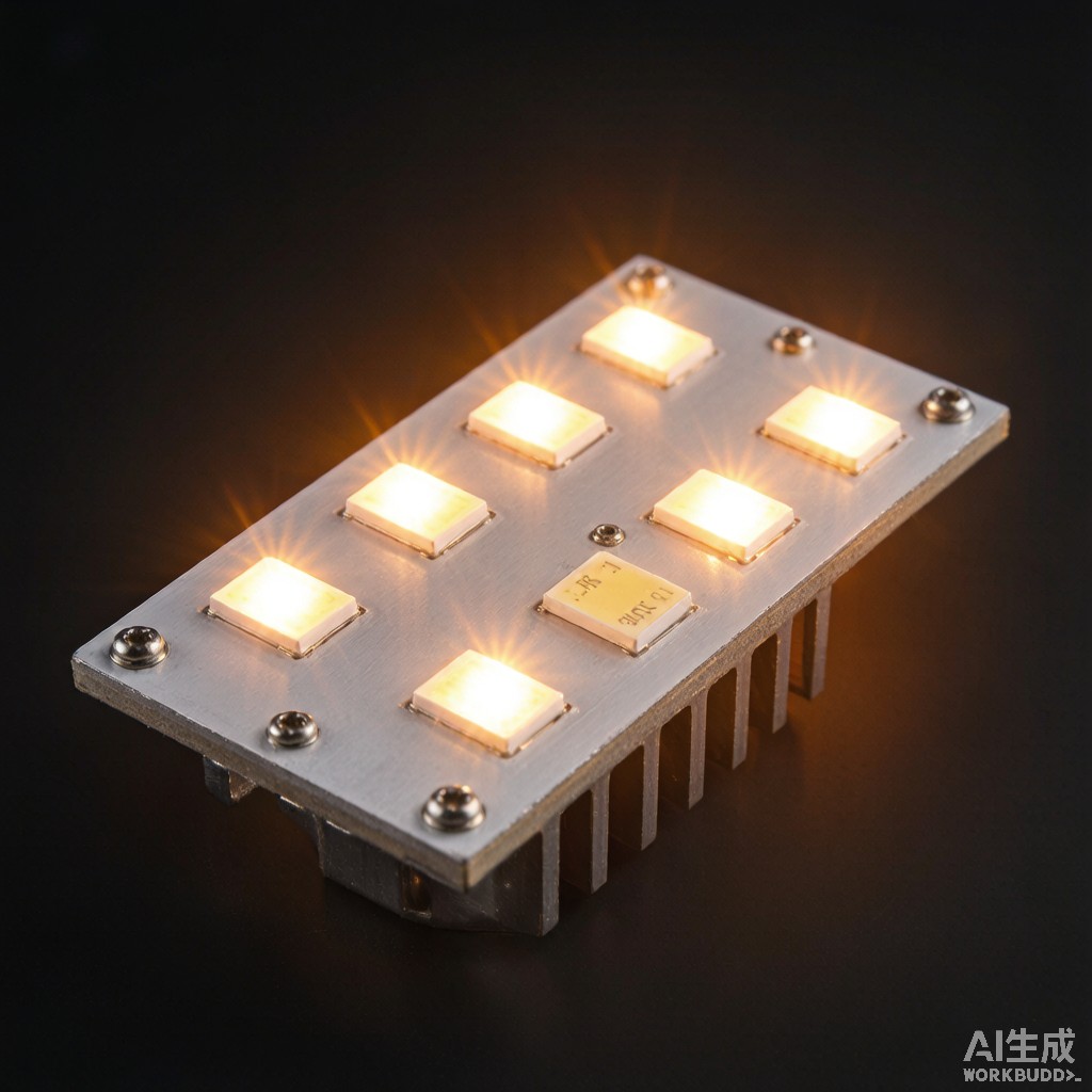
High-power SMT LED modules for street lighting, industrial high-bay fixtures, horticultural grow lights, and architectural luminaires generate heat fluxes of 0.5-3.0 W/mm² at the chip package level. Without effective thermal management, LED junction temperatures can exceed 125°C, causing lumen depreciation, color shift, and catastrophic bond-wire failure. Metal core printed circuit boards (MCPCB), also called insulated metal substrates (IMS), replace the conventional FR-4 base with an aluminum or copper plate bonded to a thin dielectric layer, reducing thermal resistance from junction to heat sink by 50-80%. This article compares aluminum-core and copper-core MCPCB technologies, dielectric thermal conductivity options, thermal interface materials, and assembly considerations for reliable high-power LED modules in tropical climates.
Why Metal Core PCB for LED Modules
Thermal Resistance Comparison
A typical 1.6 mm FR-4 PCB with 70 µm copper foil has an in-plane thermal conductivity of only 0.3-0.4 W/mK and a through-plane resistance of approximately 15-25 K·mm²/W for a 1 cm² heat source. MCPCB replaces the fiberglass-epoxy core with a 1.0-3.0 mm aluminum (237 W/mK) or copper (401 W/mK) plate separated from the circuit copper by a thermally conductive dielectric. The dominant thermal resistance becomes the dielectric itself:
| Substrate Type | Dielectric Conductivity (W/mK) | Rθ,j-board (K/W, 1 cm²) | Relative Cost |
|---|---|---|---|
| Standard FR-4 | 0.3-0.4 | 18-25 | 1.0× |
| Aluminum MCPCB, ceramic-filled dielectric | 1.0-2.2 | 3-6 | 2.5-4.0× |
| Aluminum MCPCB, high-fill dielectric | 3.0-5.0 | 1.5-3 | 4.0-6.0× |
| Copper MCPCB | 3.0-7.0 | 0.8-2 | 6.0-10.0× |
Heat Spreading and Hot-Spot Reduction
Beyond lowering through-plane resistance, the metal core acts as a lateral heat spreader. For a 3×3 mm LED package dissipating 3 W, an aluminum core can keep the temperature rise above the heat sink below 8°C, whereas FR-4 would create a 35-50°C local hot spot. This spreading allows designers to use smaller heat sinks, increase LED packing density, or extend operating lifetime by ru
ing junction temperatures closer to 85°C instead of 110°C. Copper cores are preferred for COB (chip-on-board) arrays and automotive headlamps where multiple chips share a small footprint, while aluminum cores dominate cost-sensitive general lighting.
Dielectric Layer Engineering
Thermal Conductivity vs Dielectric Strength
The dielectric layer in MCPCB is typically 75-150 µm thick and composed of epoxy resin filled with alumina (Al₂O₃), boron nitride (BN), or aluminum nitride (AlN) ceramic particles. Higher filler loading increases thermal conductivity but can reduce dielectric strength and adhesion. For 120-277 VAC mains-co
ected luminaires, dielectric strength must exceed 2-3 kV to pass UL 8750 safety testing. High-voltage designs may require a thicker dielectric (100-150 µm) even at the cost of slightly higher thermal resistance. Designers should request breakdown voltage, CTI (comparative tracking index), and UL 94 V-0 flammability data from the MCPCB supplier.
Thermal Vias and Plated Through-Holes
For SMD packages with a thermal pad on the bottom—such as high-power CSP LEDs or integrated driver ICs—thermal vias co
ect the top copper to the metal core. Because the metal core is electrically grounded or floating, via placement must avoid shorting to live copper traces. Common approaches include:
- Plated thermal vias with epoxy or non-conductive fill, capped with copper to provide a flat solderable pad.
- Plugged vias using silver-filled or copper-filled epoxy for improved conductivity and solder paste containment.
- Micro-via stacks for dense LED arrays, with via diameters of 0.2-0.3 mm and pitches of 0.8-1.2 mm under the thermal pad.
TIM, Heat Sink, and Assembly Considerations
Thermal Interface Materials
The interface between MCPCB and heat sink must fill microscopic air gaps to minimize contact resistance. Phase-change materials (PCM), thermal greases, and silicone gap pads are common choices. For outdoor tropical luminaires subject to 50-85°C ambient and daily thermal cycling, silicone-based TIMs with thermal conductivity of 3-6 W/mK offer better long-term reliability than acrylic PCMs that can pump out over time. Bond line thickness should be controlled to 0.05-0.15 mm using mechanical standoffs or dispensable TIM patterns.
Reflow and Bow Management
Aluminum and copper cores expand at approximately 23 ppm/°C and 17 ppm/°C respectively, while the top copper-dielectric stack behaves differently. During reflow at 245-260°C, this CTE mismatch can cause board bow up to 1-3 mm over 300 mm length, leading to component placement and solder joint issues. Panelization, pallet support, and symmetrical copper balance on both sides reduce bow. Some MCPCB suppliers pre-bow panels in the opposite direction so they flatten during reflow.
Reliability and Lumen Maintenance
LM-80 and TM-21 lumen maintenance projections assume a controlled junction temperature. By reducing thermal resistance with MCPCB, designers can extend L70 lifetime from 30,000 hours to 50,000-100,000 hours. For tropical installations with high ambient temperatures, selecting a copper core or high-thermal-conductivity dielectric with proper TIM and heat sink design is essential to maintain color consistency and avoid premature depreciation of the LED array.



