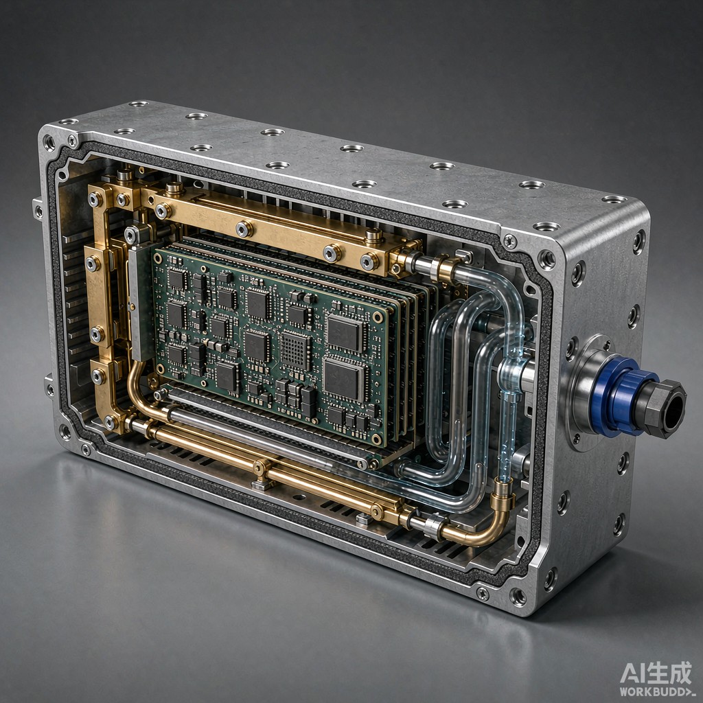
Why Liquid Cooling Is Now Mandatory at 350 Kilowatts and Above
At 350 kW the silicon-carbide inverter module dissipates 4 to 6 kW of heat into an enclosure roughly the size of a small suitcase. Forced air is no longer economical: it would require a 0.5 m diameter fan, would push the acoustic level above 75 dB(A) at one metre, and would carry dust and humidity past exposed busbars. At TechMart SE we now ship a liquid-cooled EMC enclosure as the standard power module housing for 350 kW and 720 kW DC fast chargers, with a 50/50 water-glycol coolant loop at 30 to 50 degrees Celsius and a coolant-cha
el-to-wall thermal resistance of 0.04 to 0.08 K/W.
The Three Thermal-EMC Trade-Offs You Must Solve Together
Liquid cooling and electromagnetic compliance are not independent design variables. First, coolant cha
els cut across the wall and create slot ante
as if they are not bridged by continuous metallization; second, the plastic inlet and outlet fittings act as dielectric windows unless the conductive gasket lands directly on the metal boss; third, the pump and reservoir introduce cable harnesses that can radiate common-mode noise if not filtered. Treat the EMC gasket, the coolant path, and the harness routing as a single coupled problem from day one, otherwise you will chase a 6 to 10 dB noise floor penalty through three design revisions.
Coolant Cha
el Geometry and Heat Transfer
The optimum coolant cha
el for a 600 mm by 400 mm by 200 mm enclosure is a serpentine of 12 mm diameter semicircular grooves milled into a top and bottom half-shell, with a cover plate welded or brazed on. At a flow rate of 8 to 12 litres per minute the pressure drop is 60 to 110 kPa, the wall heat transfer coefficient is 2 500 to 4 000 W per square metre per K, and the resulting SiC junction-to-coolant thermal resistance is 0.08 to 0.12 K/W per module. Pin-fin arrays and dimpled surfaces can push the coefficient to 6 000 to 8 000 W per square metre per K at the cost of a 30 to 50 percent pressure-drop penalty.
EMI Gasket Selection Under a Coolant-Soaked Environment
The gasket around the enclosure cover must seal both radio-frequency leakage and the occasional coolant drip. A beryllium-copper finger strip with a silicone tube O-ring carrier handles 100 dB shielding effectiveness at 1 GHz and 30 to 50 percent compression deflection, but the silicone needs a fluorocarbon coating if the coolant is aggressive. For a 50/50 ethylene-glycol mixture with corrosion inhibitors, an EPDM tube jacket plus a silver-aluminium elastomer gasket is the most reliable stack, delivering 90 to 95 dB at 1 GHz and 5 to 8 million compression cycles without fatigue.
Filter Pin Co
ectors and Common-Mode Chokes
Every signal and low-voltage power lead that enters or leaves the enclosure passes through a filtered D-Sub or M12 co
ector with a 100 pF to 4.7 nF feedthrough capacitor and a 1 to 10 microhenry common-mode choke. The coolant level sensor, the flow meter, and the high-voltage interlock loop each get their own filter topology, and the high-voltage DC bus uses a 0.1 to 1 microfarad Y2-class safety capacitor. The result is a conducted-emissions level 12 to 18 dB below the CISPR 25 Class 5 limit across 150 kHz to 108 MHz without an external line filter, which saves 80 to 120 USD per charger on the bill of materials.
Sealing the Coolant Path Against EMC Leakage
Plastic hose fittings are the single biggest source of radiated leakage because they create a dielectric window in the otherwise continuous metal wall. The fix is a stainless steel boss brazed or welded to the enclosure wall, with the hose crimp landing on the boss and a separate O-ring on the inside face. Add a conductive gasket under the boss shoulder to guarantee metal-to-metal contact, and the seam radiates 15 to 25 dB less than a hose clamped directly to a plastic bulkhead. Coolant leakage past a hose failure stays inside the enclosure instead of shorting the busbars.
Test Strategy and Compliance Documentation
The compliance test plan follows CISPR 25 Class 5 for radiated and conducted emissions, ISO 11452-2 for radiated immunity up to 200 V per metre, and ISO 7637-2 for conducted transient immunity on the low-voltage lines. At TechMart SE we run a 24-hour thermal soak at 50 degrees Celsius coolant inlet and 100 percent load, then repeat the full EMC sweep while the unit is hot; many designs pass at room temperature and fail at 50 degrees Celsius because the elastomer gasket softens and the seam gap grows by 0.05 to 0.10 mm. The final compliance report is a four-page document with the schematic, the gasket spec, the filtered co
ector list, and the test plots.
Specification Skeleton for a Liquid-Cooled EMC Enclosure
A robust procurement specification covers the enclosure material and wall thickness, the coolant cha
el geometry and surface finish, the gasket material and compression range, the filtered co
ector list with capacitance and inductance values, the EMC test methods, and the thermal test conditions. Include the coolant chemistry and the inhibitor package so the elastomer and the metal are both qualified. At TechMart SE the default bill of materials is 6063-T5 aluminum shell, silver-aluminium elastomer gasket with EPDM tube, and 4.7 nF X7R feedthrough capacitors on every signal pin, validated against CISPR 25 Class 5 and ISO 11452-2 at 200 V per metre. Issuing the full specification to the supplier in advance eliminates the four most common EMC-coolant integration mistakes and saves one to two design iterations.



