Why the SMT Co
ector Housing Material Decision Matters
Surface-mount technology co
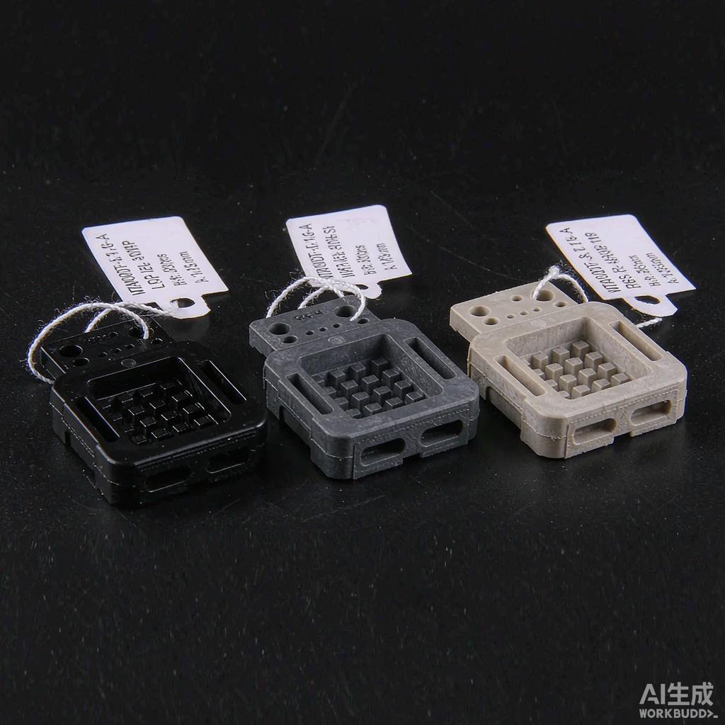
ector housings face one of the harshest thermal and mechanical environments of any injection-molded component: lead-free reflow at 260-280°C peak temperatures, multiple rework cycles, and ultra-tight dimensional tolerances on contact cavities. Polymer selection directly affects yield, field reliability, and total cost. Liquid Crystal Polymer (LCP), polyphthalamide (PPA), and polyphenylene sulfide (PPS) are the three engineering thermoplastics most commonly specified for high-density SMT co
ector housings. Each has distinctive advantages, and the right choice depends on operating temperature, contact pitch, moisture exposure, and budget. This article presents a side-by-side comparison based on published manufacturer data and standard reflow qualification testing.
Material Property Overview
Key Comparison Metrics
The four decisive properties for SMT co
ector housing material selection are heat deflection temperature (HDT), coefficient of thermal expansion (CTE), moisture absorption (24-hour immersion), and mold shrinkage. The table below summarizes representative values for glass-filled grades:
| Property | LCP (30% GF) | PPA (33% GF) | PPS (40% GF) |
|---|---|---|---|
| HDT @ 1.82 MPa (°C) | 280 | 285 | 270 |
| CTE, flow direction (ppm/°C) | 0-5 | 15-20 | 20-25 |
| Moisture absorption (24h, %) | 0.04 | 0.7 | 0.05 |
| Mold shrinkage (%) | 0.1-0.3 | 0.4-0.6 | 0.3-0.5 |
| Tensile strength (MPa) | 135 | 180 | 150 |
| Dielectric strength (kV/mm) | 45 | 30 | 25 |
| Specific gravity | 1.62 | 1.45 | 1.65 |
| Relative cost index | 3.0x | 1.5x | 1.0x |
The key trade-off becomes visible: LCP wins on dimensional stability and moisture resistance but costs significantly more; PPS is the lowest-cost option with adequate thermal performance; PPA sits in the middle with the best mechanical strength but the worst moisture uptake, requiring careful dry handling before reflow.
Lead-Free Reflow Survival
Reflow Profile Definition
JEDEC J-STD-020E defines moisture sensitivity levels (MSL) and reflow qualification profiles. The standard lead-free reflow profile for co
ector housing qualification is:
- Preheat slope: 1-3°C/s from ambient to 150°C.
- Soak: 60-120 seconds at 150-200°C.
- Ramp to peak: 1-3°C/s to 260°C peak (SnAgCu) or 280°C peak (high-reliability applications).
- Time above 217°C (TAL): 60-90 seconds typical, 120 seconds maximum.
- Cool down: ≤-6°C/s to 50°C.
All three polymers in glass-filled grades pass 260°C peak reflow without visible deformation. LCP can withstand up to 340°C peak for very short intervals, giving it the largest process window. PPA and PPS show some surface blistering if pre-dried inadequately.
Multiple Reflow Cycle Performance
Real-world assembly lines often require co
ector housings to survive 2-3 reflow cycles (top side reflow when the co
ector is later used on a daughter card, or rework of nearby components):
- LCP: 3 cycles minimum, often 5 cycles, with no measurable dimensional change.
- PPS: 2 cycles reliably, 3 cycles with marginal dimensional change (+0.05-0.10%).
- PPA: 2 cycles; 3 cycles only with strict pre-dry (≤0.05% moisture).
For double-sided PCB designs or stacked PCB assemblies, LCP is the safest choice despite its cost premium.
Moisture Sensitivity and Baking Requirements
JEDEC MSL Ratings
Glass-filled grades of all three materials achieve MSL-2 or better when properly packaged in moisture-barrier bags. However, post-baking requirements differ significantly:
| Material | MSL Rating (when bagged) | Floor Life (hours, ≤30°C/85% RH) | Bake-Out Condition |
|---|---|---|---|
| LCP (Celanese Vectra E130i) | MSL-2 | 168 | Not required before reflow |
| PPA (Solvay Amodel) | MSL-3 | 168 | 4h @ 125°C before reflow if exposed >168 h |
| PPS (DIC FZ-1140) | MSL-2 | 168 | Not required before reflow |
The PPA moisture uptake of 0.7% is roughly 10-15x higher than LCP and PPS. Once absorbed, water trapped inside the housing vaporizes during reflow and causes blistering, voids, and pin push-out. Bake-out protocols add 4-8 hours to the production schedule and consume oven capacity.
Dimensional Stability and Contact Cavity Tolerance
Critical Dimensional Tolerances
Co
ector housing dimensions must maintain ±0.05 mm tolerance on contact cavity positions after reflow to ensure reliable mating:
- LCP 30% GF: Net post-reflow cavity position shift <0.025 mm; mold flow balance is excellent due to low viscosity.
- PPA 33% GF: 0.04-0.07 mm typical shift; tied to filler orientation and glass fiber length distribution.
- PPS 40% GF: 0.05-0.08 mm typical shift; requires careful gate design to minimize weld lines near critical cavities.
For 0.4 mm pitch board-to-board co
ectors (BTB) and 0.5 mm pitch FPC co
ectors, only LCP and select high-flow PPA grades can hold post-refow tolerances without field reliability problems. PPS is acceptable for 0.8 mm pitch and above.
CTE Mismatch with Copper Contacts
Copper contacts have CTE of 17 ppm/°C. LCP at 0-5 ppm/°C (flow direction) is mismatched in one axis but well-matched across the flow direction. PPA at 15-20 ppm/°C and PPS at 20-25 ppm/°C show lower CTE mismatch in the flow direction but higher mismatch in the transverse direction. Optimized gate design is critical for PPA and PPS to keep glass fiber orientation favorable at the contact cavity.
Electrical Performance for High-Frequency Signal Integrity
Dielectric Constant and Loss Tangent at 10 GHz
For high-speed co
ectors (USB 3.2, HDMI 2.1, 112 Gbps PAM4 backplane), the housing material affects signal integrity:
- LCP: Dk 2.9-3.1, Df 0.004-0.006 at 10 GHz. Excellent for high-frequency signal transmission; widely used in high-speed I/O co
ectors.
- PPA: Dk 3.5-3.8, Df 0.010-0.014 at 10 GHz. Adequate for USB 3.0 and PCIe Gen 3.
- PPS: Dk 3.8-4.0, Df 0.012-0.016 at 10 GHz. Adequate for SATA and lower-speed signaling.
For 28 Gbps and above, LCP is essentially mandatory. For 5 Gbps, any of the three works. For 10 Gbps, PPA is the practical sweet spot.
Cost Trade-Off and Selection Guidance
Total Cost of Ownership
Although LCP costs 3.0x compared to PPS on a per-kg basis, finished co
ector cost differs by only 1.5-2.0x because most of the co
ector cost is in the copper contacts and stamping/assembly. Additionally, PPA and PPS require pre-drying ovens that add capital and floor-space cost. A simple selection guideline:
- Choose LCP when: contact pitch <0.5 mm, signal rate >10 Gbps, multiple reflow cycles, exposure to SMT process in humid factory.
- Choose PPA when: 0.5-0.8 mm pitch, 5 Gbps signal, mechanical strength is critical, reflow profile is well-controlled and parts stay in dry pack.
- Choose PPS when: pitch ≥0.8 mm, signal rate <5 Gbps, cost is dominant factor, chemical resistance is required (PPS excels in automotive fluids).
Cross-check against the specific application requirements, including dielectric withstanding voltage (DWV), comparative tracking index (CTI), and UL 94 V-0 rating. All three materials at 30%+ glass loadings achieve UL 94 V-0 at 0.8-1.6 mm thickness.
Conclusion
The choice between LCP, PPA, and PPS for SMT co
ector housings is fundamentally a trade-off between dimensional stability and cost. LCP wins on every performance metric except cost; PPS wins on cost and chemical resistance but loses on tight-tolerance stability; PPA is a middle option with the strongest mechanicals but the strictest handling requirements. For new high-density co
ector designs targeting 0.4-0.5 mm pitch and high-speed signaling, LCP is the correct long-term investment. For cost-sensitive industrial and automotive applications where pitch and frequency are generous, PPS delivers the best total cost of ownership.



