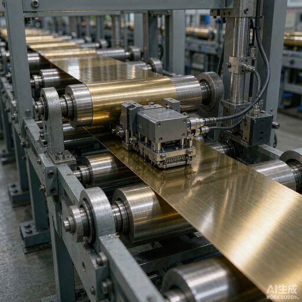
Why the Last 0.1 Percent of C19400 Hardness Variation Matters
C19400 precipitation-hardenable copper strip is the workhorse alloy for SMT lead frames, battery tabs, and high-current spring contacts, but the metallurgical recipe is unforgiving. A 10 degree Celsius overshoot in the aging furnace shifts the final Vickers hardness by HV 8 to 15, and the corresponding electrical conductivity drops by 3 to 6 percent IACS. At TechMart SE we have replaced traditional lot-based mechanical testing with a continuous in-line eddy current array that maps every metre of strip at full production speed.
The Physics of Eddy Current on Copper Strip
An eddy current probe drives an alternating current through a coil at frequencies from 30 kHz to 2 MHz, generating an alternating magnetic field that couples into the conductive strip moving past the probe head. The induced eddy currents in the strip produce a secondary field that opposes the primary, and the resulting impedance change carries information about conductivity, permeability, and the geometry of the strip. For a non-magnetic copper alloy, the response simplifies to two calibration variables: electrical conductivity in percent IACS and a phase component that tracks hardness through its influence on dislocation density.
Probe Selection and Calibration Standards
For 0.20 to 0.50 mm C19400 strip at 30 to 120 m/min, a single-cha
el absolute probe with a 4 to 6 mm tip diameter gives the best signal-to-noise ratio. Calibration uses three to five reference samples whose conductivity and hardness are traceable to NIST test blocks, typically covering 60 to 90 percent IACS and HV 110 to 170. The probe is mounted in a non-metallic holder at 0.5 to 1.0 mm lift-off, with the lift-off variation held under plus or minus 0.05 mm by precision roller alignment.
Mapping Hardness Through Conductivity
The classical aging response of C19400 is that hardness peaks while conductivity continues to climb, because the Fe2P and Fe3P precipitates scavenge iron from solid solution and lower the lattice strain that scatters electrons. A properly aged strip at 450 to 500 degrees Celsius for 2 to 4 hours typically lands at HV 130 to 150 with 70 to 78 percent IACS. Our empirical correlation table for 0.30 mm strip shows that conductivity below 65 percent IACS correlates with under-aged material, while conductivity above 82 percent IACS correlates with over-aged material. The eddy current map flags both out-of-spec zones for the operator within 200 ms of the strip leaving the aging furnace.
Why Sampling-Based QA Misses Real Defects
Lot-based mechanical testing pulls one sample per 500 to 1 000 kg of strip, which means a 0.5 metre defect window is statistically invisible. The most common defect in continuous a
eal furnaces is a 200 to 800 mm section where the strip temperature drifted 15 to 30 degrees Celsius because of a partial heater failure or a strip-speed transient. The eddy current array flags these defects in real time, allowing the operator to mark the suspect section with an ink-jet marker and divert it to a re-aging or down-grade path before it ships to the customer.
Integration with SPC and the Customer Certificate
Every coil of strip we ship carries a 1-metre-resolution conductivity and hardness map in CSV format, plus a summary plot showing the minimum, maximum, mean, and standard deviation across the coil. The data feeds the customer’s statistical-process-control chart and supports the AEC-Q100 qualification on automotive programs. For medical and aerospace customers we add a hard-copy certificate traceable to the original NIST calibration block. The whole QC loop is closed within 30 minutes of the strip being coiled, faster than the lot-based mechanical test cycle that historically took 8 to 12 hours.
Practical Spec Skeleton for an Eddy Current QA Line
An eddy current QA specification is most robust when it states the probe model and frequency, the calibration block traceability, the lift-off tolerance, the strip-speed range, the alarm thresholds for conductivity and hardness, the data retention format, and the operator-marking method for out-of-spec zones. At TechMart SE the default is a 1 MHz absolute probe calibrated against NIST-traceable conductivity samples at 40, 60, 80, and 100 percent IACS, plus four Vickers reference blocks covering HV 110 to 170. Issuing the spec to the line in advance prevents the four most common commissioning disputes, namely probe temperature drift, lift-off variation, calibration drift over a shift, and signal-to-noise on highly polished strip finishes.
Operator-Facing Acceptance Criteria and What Happens on a Flag
The acceptance criteria for a passing coil are simple: the minimum and maximum conductivity must sit within 65 to 82 percent IACS, the minimum and maximum Vickers hardness must sit within HV 110 to 170, and the standard deviation across the coil must be under 1.5 percent IACS and HV 3. When a section of strip flags outside the window, the operator marks the coil with a coloured ink-jet at the suspect zone, and the section is physically cut and re-routed. A 0.5 m flagged section in a 1 500 m coil is acceptable for many end uses; a 5 to 10 m flagged section is re-aged or down-graded to a lower-cost product family. The audit trail for every flagged event is automatically written to the SQL database and is available to the customer for any subsequent quality claim.



