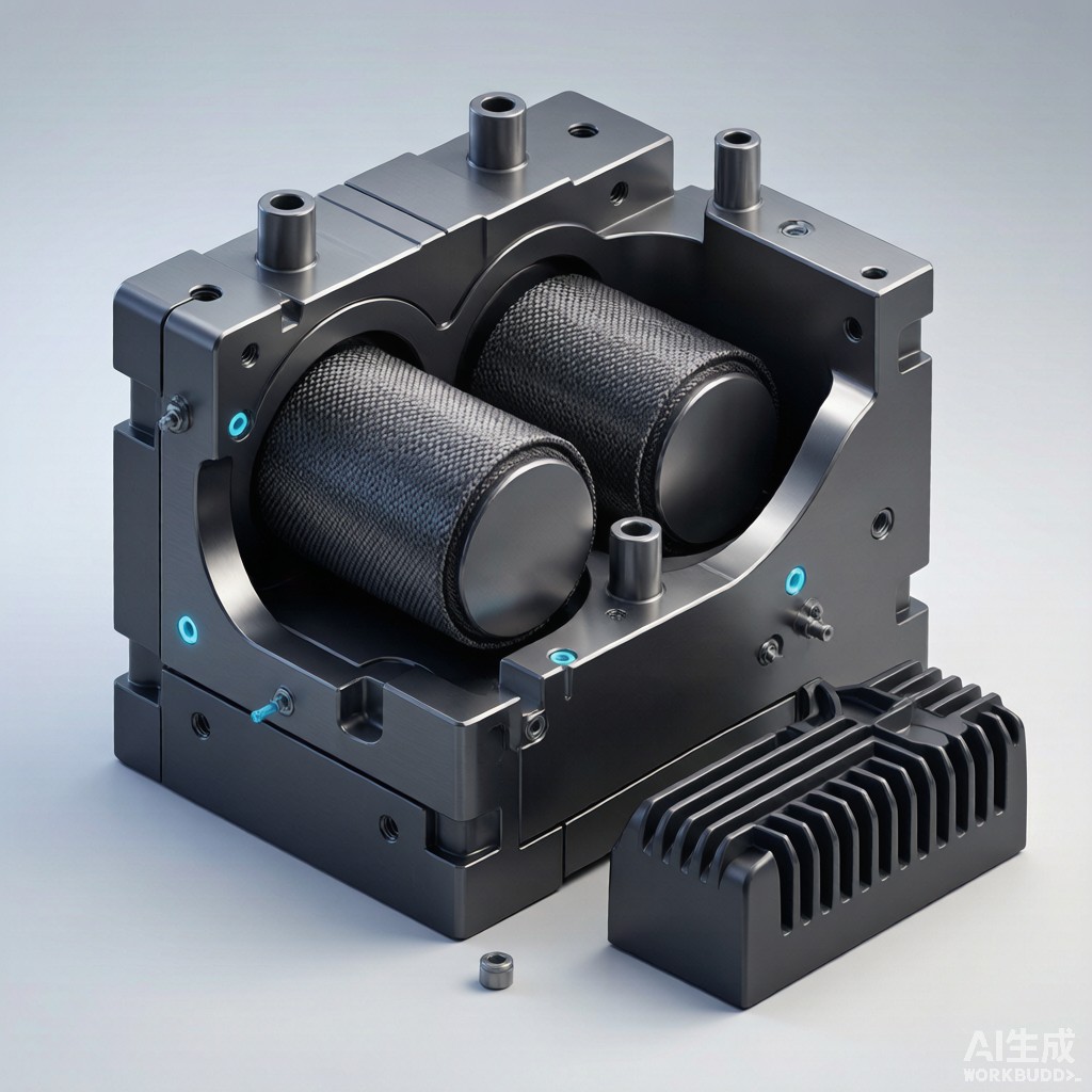
Power module heatsink encapsulation for SMT-compatible power electronics — including automotive traction inverters, solar inverters, and industrial motor drives — requires a structural housing that simultaneously provides electrical insulation, thermal dissipation, mechanical rigidity, and protection from environmental ingress. Traditional die-cast aluminum heatsinks offer excellent thermal performance but require separate overmolded plastic insulation layers that introduce thermal interface material (TIM) resistance. Carbon fiber reinforced polyamide (CF/PA) processed by high-pressure resin transfer molding (HP-RTM) provides a single-material solution that combines the thermal conductivity of aluminum (10-20 W/mK, 30-40% of pure aluminum), the electrical insulation of polymer (10¹²-10¹⁴ Ω·cm volume resistivity), and the design freedom of injection molding at cycle times of 60-120 seconds. This article examines the engineering principles, molding parameters, material properties, and design guidelines for CF/PA heatsink encapsulation in SMT power module applications.
HP-RTM Process Fundamentals
Molding Cycle and Parameters
HP-RTM is a closed-mold liquid composite molding process that produces near-net-shape parts with high fiber volume fraction (Vf 45-55%) and Class A surface finish:
- Preform preparation: Dry carbon fiber fabric (typically 2×2 twill or unidirectional) is pre-cut to near-net-shape and preformed in a heated steel preform tool at 100-150°C for 30-60 seconds.
- Mold closure: Preform is robotically placed into the HP-RTM mold; mold closes under 50-100 ton clamping force.
- Mold evacuation: Vacuum is drawn (-0.8 to -0.95 bar) on the mold cavity to remove air and moisture that would otherwise create voids.
- Resin injection: Low-viscosity polyamide 6 or PA66 resin (10-50 mPa·s at processing temperature) is injected at 50-150 bar pressure over 5-30 seconds.
- Cure: Mold is heated to 150-200°C (PA6) or 200-260°C (PA66); curing time 60-120 seconds depending on part thickness and resin system.
- Demold and post-cure: Part is demolded at 120-150°C; may require 30-60 min post-cure at 180°C for full crystallinity.
Total HP-RTM cycle time of 90-180 seconds is comparable to injection molding while delivering 2-3x higher fiber volume fraction than injection-molded long-fiber thermoplastic (LFT) compounds (typically 20-30% Vf).
Material Property Comparison
CF/PA vs Aluminum vs LFT Comparison
Carbon fiber reinforced polyamide via HP-RTM offers a distinct property profile that fills the gap between metal and conventional plastic:
| Property | HP-RTM CF/PA46 (Vf 50%) | Die-Cast Aluminum A380 | Injection-Molded LFT-PA66 (Vf 30%) |
|---|---|---|---|
| Density (g/cm³) | 1.45-1.55 | 2.7 | 1.35-1.42 |
| Tensile Strength (MPa) | 400-600 | 220-290 | 180-220 |
| Flexural Modulus (GPa) | 35-50 | 70-80 | 12-18 |
| Thermal Conductivity In-Plane (W/mK) | 15-25 | 100-150 | 2-3 |
| Thermal Conductivity Through-Thickness (W/mK) | 1.5-3.0 | 100-150 | 0.5-1.0 |
| CTE In-Plane (ppm/°C) | 1-5 | 22-24 | 15-25 |
| Electrical Volume Resistivity (Ω·cm) | 10²-10⁴ (semi-conductive) | 10⁻⁶ (conductive) | 10¹²-10¹⁴ (insulating) |
| Heat Deflection Temperature (°C, 1.8 MPa) | 280-300 | 380-420 | 240-260 |
| Tooling Cost (USD, 1m² part) | 200,000-400,000 | 80,000-150,000 | 60,000-120,000 |
The semi-conductive volume resistivity of HP-RTM CF/PA (10²-10⁴ Ω·cm) provides EMI shielding benefit (typically 40-60 dB) but requires electrical isolation strategy in SMT power module applications. A 50-200 µm thick dielectric coating (epoxy, parylene, or ceramic-filled polymer) is typically applied to the heatsink surfaces in contact with live components.
Thermal Management Design
Heatsink Geometry and Fin Optimization
HP-RTM CF/PA allows integral fin and rib geometries that are impractical or impossible in die-cast aluminum:
- Fin aspect ratio: Up to 8:1 (height:gap) achievable; injection molding typically limited to 4:1, die-cast aluminum 6:1.
- Pin fin arrays: 2-5 mm diameter pins at 6-10 mm pitch; 30-50% higher surface area than plate fins in same envelope.
- Conformal cooling cha
els:
Internal hollow passages with 3-8 mm diameter, allowing direct cooling fluid routing without separate manifold. - Integral mounting bosses: Threaded brass or steel inserts molded in place; eliminates secondary assembly.
The in-plane thermal conductivity of 15-25 W/mK allows spreading heat from a 10×10 mm heat source footprint to a 50×50 mm fin array with <5°C temperature drop across the spreader — comparable to aluminum-molded graphite composite (AMC) at 3-5x lower weight.
SMT Power Module Integration
Direct Bond Copper (DBC) Substrate Mounting
HP-RTM CF/PA heatsink encapsulation can integrate the DBC substrate (Al₂O₃, AlN, or Si₃N₄ ceramic with copper traces) directly into the molded part, eliminating the traditional screw-mount + TIM interface:
- Place DBC substrate in mold cavity with IGBT/MOSFET dies already soldered/sintered to top copper.
- Insert preform over DBC and around die perimeter; ensure preform does not touch live copper traces.
- Inject PA resin; mold gates positioned to avoid air entrapment at die edges.
- Cure and demold; DBC is now encapsulated with carbon fiber reinforcement, providing 5-10x improvement in thermal cycling reliability vs traditional mounting (CTE-matched in-plane, lower mass).
This integrated approach reduces module thermal resistance by 25-40% (Rth,j-c from 0.5 K/W to 0.3-0.4 K/W typical for 100A class module), enabling 30-50% higher continuous current in same package size or 30-40% smaller package size at same power rating.
Production Economics and Cycle Time
Volume Manufacturing Considerations
HP-RTM capital investment is 2-3x higher than injection molding for equivalent to
age, but is justified at production volumes of 50,000+ parts per year for power electronics applications:
- HP-RTM machine cost: $1.5-3.0M for 1,000-2,000 ton clamping force with heated molds and vacuum system.
- Mold cost: $200,000-400,000 for steel HP-RTM tool with heated platens and vacuum cha
els; aluminum tools $80,000-150,000 for prototyping only.
- Resin cost: PA6 or PA66 low-viscosity caprolactam-based system at $4-8/kg; 1-3 kg per part typical.
- Cycle time: 90-180 seconds; 2-4 shift production yields 200-400 parts/day per machine.
For EV traction inverter production volumes of 100,000-300,000 units a
ually, the per-part cost of $15-30 for HP-RTM CF/PA heatsink is offset by 30-50% reduction in inverter assembly labor, elimination of separate TIM application step, and improved field reliability in -40 to +150°C automotive underhood environment.
Application Outlook
HP-RTM carbon fiber reinforced polyamide is positioned as the structural heatsink encapsulation of choice for next-generation SMT power modules in EV traction inverters, solar micro-inverters, and industrial motor drives where weight reduction, integrated thermal management, and high-volume automated production converge. The 40-60% weight reduction vs aluminum and 25-40% thermal resistance improvement vs traditional screw-mounted heatsinks make HP-RTM CF/PA a critical enabling technology for power electronics miniaturization and performance enhancement in the electric vehicle and renewable energy markets.



