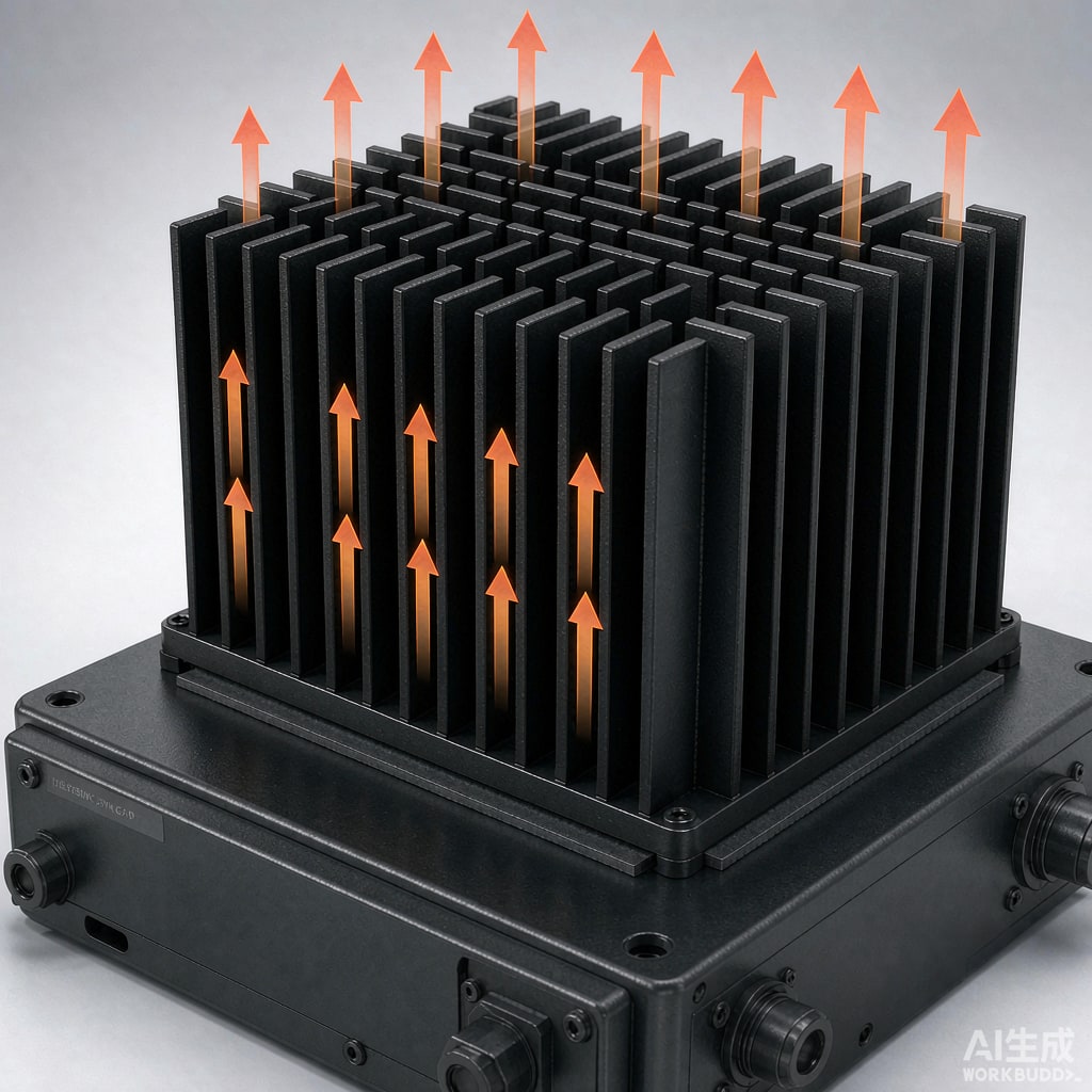
In fanless products — industrial controls, telecom outdoor units, LED drivers, set-top boxes — heat sinks rely entirely on natural convection and radiation. Unlike forced-air designs, where packing more fin area always helps, natural convection has a built-in compromise: fins that are too close choke off the very air buoyancy depends on. Getting fin spacing and orientation right is the difference between a heat sink that works and one that is mostly decorative aluminum.
Why Buoyancy Changes the Design Rules
Natural convection moves air because heated air becomes less dense and rises. The airflow velocity is not imposed by a fan; it emerges from the temperature difference itself, typically only 0.1–0.5 m/s at the fin surfaces. With such weak driving pressure, the viscous boundary layers on adjacent fins easily merge if the gap between fins is small. When boundary layers merge, the air between fins becomes stagnant and effectively insulated — added fin area beyond that point transfers almost no heat while adding weight and cost.
The optimum gap
For a vertical plate-fin heat sink 50–100 mm tall in typical indoor conditions, the classic recommendation is a fin gap of 6–10 mm. Shorter sinks (below ~40 mm) can tolerate 4–6 mm gaps; taller sinks need progressively wider gaps because boundary layers thicken along the height. A useful first-pass rule for vertical fins in air at room temperature: optimal gap in mm ≈ 0.06 × (fin height in mm) to the power of roughly 0.75, which for a 100 mm tall fin gives about 7–8 mm. Extrusion manufacturers’ natural-convection catalogs are built around these numbers — a 50 mm tall sink with 3 mm gaps performs worse than a shorter sink with 8 mm gaps, because most of its cha
els are dead.
Orientation: The Most Ignored Variable
Vertical fins, vertical base
The best case is a heat sink mounted so its fins are vertical and the cha
els run vertically, allowing air to rise freely through the cha
els. Many enclosures achieve this naturally by standing PCBs vertically in card cages. Where the base must be horizontal, the fins should still extend vertically, not lie flat.
Horizontal and bad orientations
A fi
ed sink lying with fins horizontal (cha
els ru
ing sideways) loses 20–30% of its natural convection performance. Worst of all is a sink mounted facing upward with fins forming horizontal pockets: warm air is trapped in the cha
els and must exit sideways with almost no driving force, costing 30–40% performance. If product geometry forces a bad orientation, compensate by widening fin gaps and reducing fin count — fewer, wider cha
els beat many narrow ones in every non-vertical orientation. Rotating the sink 90° in the same enclosure can matter more than doubling its volume.
Fin Height, Thickness, and Radiating Surface
Beyond spacing, fin effectiveness declines with height: a very tall thin fin carries heat poorly to its tip. For aluminum extrusions, fin height-to-gap ratios of 6–12 are typical for natural convection, and fin thickness of 1.5–3 mm keeps conduction losses acceptable. Do not forget radiation: in natural convection, radiative transfer can contribute 25–40% of total dissipation, especially for the base and fin tips facing the enclosure. Anodized black finishes raise emissivity from ~0.1 for bare aluminum to ~0.8–0.9, effectively buying extra cooling capacity for nearly zero cost. Inside sealed enclosures, also plan internal airflow paths so air heated by the sink can rise and exit past vents near the top of the box, while makeup air enters low.
Enclosure-level thinking
A common mistake is designing the heat sink in isolation and then burying it inside a sealed case. In a sealed enclosure the heat sink’s job is first to move heat from component to air inside the box, and then the box walls reject heat to ambient. The internal sink helps, but wall area, wall material, and external paint color end up controlling the final temperature. For high-power fanless designs, evaluate whether the enclosure itself should act as the heat sink — fins on the housing exterior, component-to-wall thermal paths — rather than a conventional sink sitting on the PCB.
Design Checklist
- Vertical fin cha
els with air rising freely — avoid horizontal pockets wherever geometry allows.
- Fin gap 6–10 mm for typical 50–100 mm tall sinks; scale gap with fin height.
- Fin height-to-gap ratio 6–12; fin thickness 1.5–3 mm for extrusions.
- Black anodize or paint for emissivity — radiation is 25–40% of natural convection cooling.
- If orientation is compromised, widen gaps and drop fin count.
- Design enclosure vents high and low to sustain the buoyancy draft through the sink.
- Validate with a thermocouple on the base plate at worst-case ambient — spreadsheet predictions are only first-pass.
Conclusion
Natural convection rewards restraint: fewer fins, wider gaps, vertical cha
els, and a black finish usually outperform a dense fin pack that looks more impressive. Because the available pressure head is only a few pascals, every design decision that restricts airflow — narrow cha
els, horizontal pockets, blocked vents — is paid for directly in component temperature. Respect buoyancy and it will quietly carry away heat without a single moving part or a single watt of fan power.



