Attachment Is Half the Thermal Design
Engineers obsess over heat sink fin geometry and TIM choice, then sabotage both with poor attachment. The thermal path from a QFN or D2PAK junction to the heat sink base passes through two resistances you control by mechanical design: the TIM bulk resistance (set by thickness and coverage) and the contact resistance at each interface (set by pressure). An under-clamped thermal pad can double the interface resistance of a well-clamped one, because air gaps — the worst conductor in the stack — survive wherever pressure is absent. Choosing an attachment method is choosing your pressure map, your rework story, and your failure modes.
Spring Clips and Wire Clips
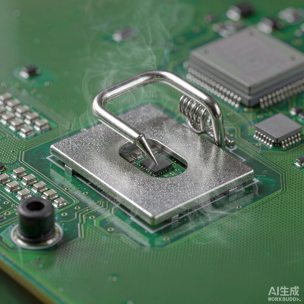
Stamped spring clips, usually stainless or spring steel wires formed to press on the heat sink over the component, are the lightest and cheapest option for SMD-scale sinks. A clip hooks onto PCB anchors (soldered-in standoffs, L-shaped pins, or plated through-holes) and converts its deflection into clamping force. Properly designed, they deliver uniform pressure directly over the die — better centered than screws, which push down at the sink corners. They add no torque-critical assembly steps and survive vibration without loosening, since the spring maintains force through thermal cycling.
Their weaknesses are structural: clamping force is limited by wire strength and deflection (typically a few tens of newtons, adequate for TIM pads on parts up to roughly 5 W dissipation), and they need anchor features designed into the PCB and the sink from day one. Retrofitting clips onto an existing layout is rarely possible.
Push Pins and Plastic Anchors
Push-pin attachment uses plastic or metal pins through the heat sink and board into barbed anchors underneath — the classic method on graphics cards and telecom boards. Assembly is fast, tool-free, and pressurizes the interface at a consistent, pre-set deflection. The catch: the pins occupy board real estate (through-holes and anchor keepouts on the backside, typically 2–4 mm per pin), and clamping force depends entirely on pin design. Standard plastic push pins deliver modest pressure — often insufficient for higher-performance phase-change or graphite TIMs that need 20–50 psi to seat properly. Rework is acceptable: pins pull out with pliers, and the sink lifts clean.
Spring Screws and Standoffs
For heavy sinks and high-power devices, spring-loaded screws over captive compression springs are the precision option. The spring defines the clamping force independent of torque skill — you tighten until the washer seats, and the spring delivers its designed force (commonly 50–150 N per screw for power modules). This is the standard for IGBT modules, where uneven pressure warps the module base and cracks solder die. Two rules matter. First, use the screw count and pattern the manufacturer specifies — usually four, tightened in a diagonal sequence to a defined torque. Second, verify the spring rate and compression: over-torquing a spring screw beyond full compression converts it into a rigid clamp and can crack ceramic substrates.
Screws require backside access or bosses on the board, add assembly cost, and — under vibration — need thread-locking or wedge washers. But for anything above roughly 20 W, the controlled pressure is worth it.
Thermally Conductive Adhesives and Tapes
Adhesive attachment bonds the sink permanently: one- or two-part thermally conductive epoxies (filled with alumina or silver, curing at room temperature or 80–150°C) or high-performance acrylic transfer tapes. Adhesives shine where there is no mechanical anchor path — plastic housings, single-sided boards, tight spaces. They add zero fastener mass, seal the interface against dust, and survive vibration superbly.
The trade-offs are serious. Rework: an epoxied sink generally destroys the component or pad on removal; if field service is possible at all, plan for heated blade removal and accept the scrap. CTE stress: a rigid epoxy bridging aluminum and FR-4 experiences shear stress over thermal cycling; choose a lower-modulus, rubber-toughened adhesive or a compliant tape for large sinks or wide temperature swings. Pressure during cure: adhesives need a fixture weight or clamp for the cure period — a bond line formed without pressure is full of voids. Acrylic tapes (the family used in LED lighting) are the friendlier option: they wet under firm hand pressure, handle rework with heat and slow peel, and need no cure time.
Choosing and Validating
A simple selection ladder: under about 5 W, spring clip with a performance TIM pad; 5–20 W, push pins if board space allows, or tape if rework is expected; above 20 W, spring screws over the die or a baseplate. Whatever you choose, validate three things. First, pressure coverage: assemble with a pressure-indicating film or a witness TIM and confirm the footprint printed under the sink matches the pad outline — voids at the die location are the classic hidden defect. Second, thermal cycle and vibration per your product environment; clips and screws should show no force decay, adhesives no delamination. Third, measure the delta-T across the interface in the first-article thermal test — if the sink-to-case temperature rise exceeds your model by more than 20–30%, suspect attachment before you suspect the TIM.



