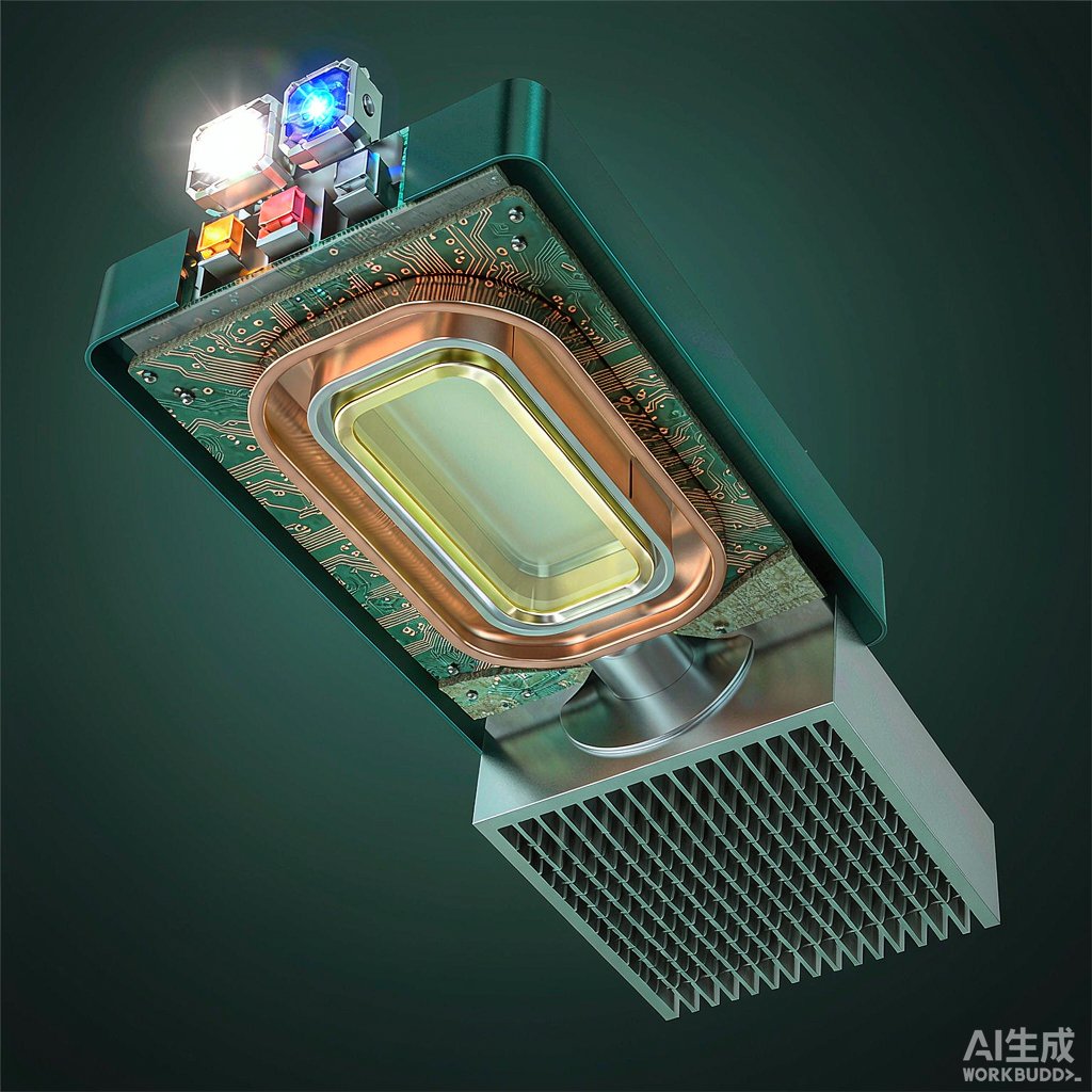
The Heat Density Challenge in Modern LED Modules
High-power LED modules for automotive headlamps, horticultural lighting, stadium projectors, and UV curing systems now generate more than 200 watts per square centimeter at the chip level. Removing that heat through a conventional FR4 or metal-core PCB limits junction temperature and forces LED derating. Heat pipe embedded PCBs offer a passive, two-phase cooling solution that dramatically increases effective thermal conductivity without adding fans or pumps.
Unlike a separate heat pipe bolted to a metal-core PCB, an embedded design integrates the heat pipe directly into the laminate structure during PCB fabrication. This article explains how embedded heat pipe PCBs work, what materials are involved, and what design rules engineers should follow.
How a Heat Pipe Embedded PCB Works
Two-Phase Heat Transfer Principle
A heat pipe operates by vaporization and condensation of a working fluid inside a sealed cavity. Heat applied at the evaporator section vaporizes the fluid; the vapor travels to the cooler condenser section where it condenses, releasing latent heat. A capillary wick returns liquid to the evaporator by capillary action. Effective thermal conductivity ranges from 5,000 to 50,000 W/m·K, hundreds of times higher than solid copper.
Why Embed It in the PCB
Embedding the heat pipe directly into the PCB places the evaporator inches from the LED die. This short thermal path reduces spreading resistance and allows LED arrays to operate at higher drive currents. The condenser end can be tied to a remote aluminum heat sink, an aluminum substrate, or a chassis-mount cold plate. Embedded designs also simplify assembly because the cooling layer is part of the PCB itself.
PCB Construction and Material Selection
Copper-Inlay Cavities
Heat pipe embedded PCBs are built on FR4 or high-Tg FR4 cores with milled or laser-cut cavities. A flat copper heat pipe is bonded into the cavity using thermally conductive prepreg or epoxy. Copper is preferred for the pipe body because it is compatible with PCB lamination temperatures up to 200 degrees Celsius and offers excellent burst strength.
Wick Structure Options
Common wick structures include sintered copper powder, grooved axial cha
els, and composite felt. Sintered wicks provide high capillary pressure, ideal for horizontal orientation against gravity. Grooved wicks have lower flow resistance but limited capillary lift. For LED modules with the heat pipe oriented horizontally, sintered wicks are usually the best choice.
Working Fluids
Working fluids are chosen based on operating temperature. Water-filled heat pipes operate between 30 and 200 degrees Celsius and offer the highest figure of merit for LED applications. For high-temperature LED modules above 150 degrees Celsius, acetone or methanol-based fluids may be used, though they have lower thermal transport capacity.
Thermal Design Rules
Heat Pipe Placement Under LED Arrays
Place the heat pipe evaporator section directly under the LED array thermal pad. Multiple short heat pipes in parallel distribute heat more evenly than one long pipe. Keep the evaporator length at least two to three times the LED array width to allow uniform heat absorption and prevent dry-out under high heat flux.
Condenser Interface
The condenser end is typically clamped or soldered to an external heat sink. Use thermal interface material rated for the expected temperature range, and apply uniform clamp pressure to avoid local dry-out. If the condenser is integrated with a metal substrate, verify that lamination temperature does not exceed the heat pipe’s working fluid saturation limit.
Avoiding Dry-Out
Dry-out occurs when vapor generation exceeds the wick’s ability to return liquid. To prevent this, do not exceed the heat pipe’s heat transport limit (Qmax) and avoid operating at temperatures above the fluid’s critical point. For water-filled pipes on LED modules, keep maximum heat flux below 50 W/cm² in the evaporator.
Reliability and Testing
Thermal Cycling
Embedded heat pipes must survive thousands of thermal cycles between -40 and +125 degrees Celsius. The thermal expansion mismatch between copper pipe and FR4 can delaminate the laminate if CTE is not controlled. Use low-CTE prepreg or symmetric stack-ups to keep stress balanced across the PCB.
Leak Testing
Each heat pipe must be helium leak tested to less than 1×10⁻⁸ atm·cc/s before lamination. Even tiny leaks cause gradual fluid loss and degrade performance over years of operation. Production-grade helium leak testing is essential for automotive-grade LED modules.
Application Snapshots
Automotive headlamp PCBs with embedded heat pipes allow 50 W LEDs to run at junction temperatures below 120 degrees Celsius without active fans. Horticultural top-lighting fixtures use embedded heat pipes to keep full-spectrum LED arrays cool enough for stable photosynthetic photon flux density. Industrial UV curing modules achieve continuous 365 nm output at high power densities thanks to embedded two-phase cooling.
For LED module designers evaluating cooling options, embedded heat pipe PCBs offer an excellent balance of passive reliability, low acoustic noise, and high effective thermal conductivity. Combined with proper wick selection, working fluid choice, and conservative thermal design margins, this technology enables next-generation lighting products.



