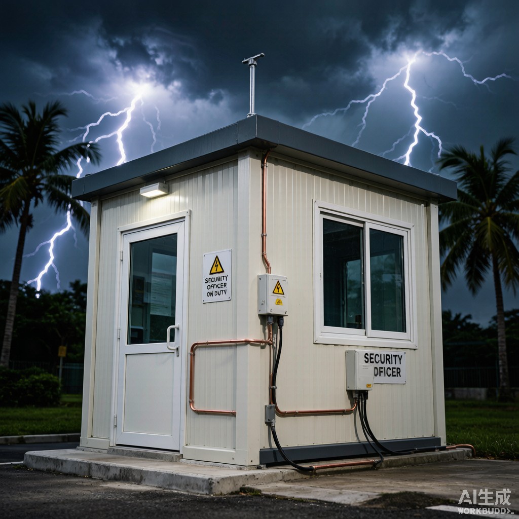
Introduction: Guard Booths in the Lightning Capital of the World
Southeast Asia sits within the most lightning-active region on Earth. Indonesia experiences an average of 100-200 thunderstorm days per year, with the Java Sea region recording some of the highest ground flash densities globally — exceeding 30-50 flashes per km² per year. Malaysia, Thailand, and the Philippines similarly experience 100-180 thunderstorm days a
ually. For prefabricated guard booths installed at industrial facilities, construction sites, and infrastructure checkpoints throughout this region, lightning protection is not an optional accessory — it is a life-safety requirement.
A guard booth is a small, often metal-ski
ed structure occupied by a single security guard for extended shifts. When lightning strikes nearby, the booth’s metal frame can become energized to high voltages, interior electronics can be destroyed by induced surges, and the occupant can be exposed to touch and step potentials that cause injury or death. This article examines the engineering design of lightning protection and surge suppression systems specifically for guard booths in tropical thunderstorm zones.
Lightning Risk Assessment for Guard Booths
IEC 62305-2 Risk Calculation
The IEC 62305-2 standard provides a quantitative risk assessment methodology for determining whether a structure requires lightning protection and what level of protection is appropriate. The key risk components for a guard booth:
R1 (Risk of loss of human life): This is the dominant risk for occupied guard booths. The risk is calculated from the a
ual lightning flash density (Ng), the equivalent collection area of the structure (Ae), the probability of strike (Pd), and the probability of injury given a strike (Pa). For a typical 2.5 m × 2.5 m × 2.5 m guard booth in a region with Ng = 30 flashes/km²/year, the calculated risk of human loss without protection exceeds the tolerable risk threshold (RT = 10⁻⁵) by a factor of 10-50.
R2 (Risk of loss of service): Relevant for booths housing security electronics (CCTV, access control, communication equipment). Lightning-induced surges can damage sensitive electronics, disrupting security operations.
R3 (Risk of loss of cultural heritage): Not applicable to guard booths.
R4 (Risk of loss of economic value): Includes cost of equipment damage and downtime. For booths with $5,000-15,000 of electronics, this risk is typically acceptable but should be evaluated.
Southeast Asian Lightning Density Data
| Country/Region | Thunderstorm Days/Year | Ground Flash Density (Ng) | Required Protection Level |
|---|---|---|---|
| Indonesia (Java) | 180-220 | 30-50 flashes/km²/yr | Level I (highest) |
| Indonesia (Sumatra) | 150-180 | 20-35 flashes/km²/yr | Level I-II |
| Malaysia (Klang Valley) | 140-180 | 25-40 flashes/km²/yr | Level I |
| Thailand (Central) | 100-140 | 15-25 flashes/km²/yr | Level II |
| Philippines (Manila) | 100-150 | 15-30 flashes/km²/yr | Level II |
| Vietnam (Ho Chi Minh) | 90-120 | 10-20 flashes/km²/yr | Level II-III |
For most Southeast Asian deployments, guard booths require Lightning Protection Level (LPL) I or II, corresponding to a protection efficiency of 98% or 95% respectively. Level I is recommended for Indonesia and Malaysia; Level II for other SE Asian countries.
Air Termination System Design
Rolling Sphere Method
The rolling sphere method is the primary technique for positioning air terminals (lightning rods) on structures. For LPL I, the sphere radius is 30 m; for LPL II, it is 45 m. The principle: a sphere of the specified radius rolled over the structure in all possible directions should not touch any point on the structure without first touching an air terminal.
For a guard booth with dimensions 2.5 m × 2.5 m × 2.5 m, a single Franklin air terminal (vertical rod) mounted on the roof center with a height of 0.5-1.0 m above the roofline provides complete coverage under both LPL I and LPL II. The protection radius at roof level for a 1.0 m terminal under LPL I (30 m sphere) is calculated as:
r = √(2hR – h²) = √(2 × 1.0 × 30 – 1.0²) = √59 ≈ 7.7 m
This 7.7 m protection radius far exceeds the 1.77 m diagonal of the 2.5 m × 2.5 m booth roof, providing ample coverage margin.
Air Terminal Material and Construction
The air terminal must withstand direct lightning attachment without melting, vaporizing, or being structurally damaged. For Level I protection (200 kA peak current, 10/350 μs waveform), the minimum cross-section for a solid copper air terminal is 50 mm² (approximately 8 mm diameter). For stainless steel, the minimum is 75 mm² (approximately 10 mm diameter). In tropical coastal environments, stainless steel (316L) is preferred over copper due to corrosion resistance — copper air terminals can develop verdigris that increases contact resistance at the base co
ection.
The air terminal should be mounted on a non-conductive base (polyamide or glass-reinforced plastic) to prevent side-flash from the terminal to the booth’s metal roof structure. The base must have sufficient dielectric strength to withstand the lightning impulse voltage (typically 1-2 MV at the terminal base during a 200 kA strike).
Down Conductor and Bonding System
Down Conductor Sizing and Routing
For a steel-frame guard booth, the booth’s structural steel frame itself can serve as a natural down conductor if properly bonded and of sufficient cross-section. IEC 62305-3 permits the use of structural steel as a down conductor if the cross-sectional area is at least 50 mm² (copper equivalent) and all joints are electrically continuous with bolted or welded co
ections having a contact area of at least 50 mm².
For booths with non-conductive wall panels (such as sandwich panels with aluminum skins), at least two dedicated down conductors are required, routed on opposite corners of the booth. Minimum cross-sections:
| Conductor Material | Min Cross-Section (LPL I) | Min Cross-Section (LPL II) | Typical Construction |
|---|---|---|---|
| Copper (stranded) | 50 mm² | 35 mm² | Class II stranded, PVC insulated |
| Copper (solid tape) | 50 mm² (25×2 mm) | 35 mm² (20×2 mm) | Bare or PVC-sheathed |
| Aluminum (stranded) | 80 mm² | 56 mm² | Not recommended for direct burial |
| Stainless steel (solid) | 75 mm² | 50 mm² | 316L for tropical coastal use |
In tropical environments, copper down conductors should be PVC-sheathed or installed in UV-resistant conduit to prevent corrosion. The conductor should be routed externally (not inside the booth interior) to prevent side-flash to the occupant during a lightning event.
Grounding System Design
Tropical Soil Resistivity Challenges
Southeast Asian tropical soils present challenging grounding environments. Lateritic clays, common in Malaysia and Indonesia, have resistivities of 100-500 Ω·m when moist but can exceed 1,000 Ω·m during dry seasons. Coastal sandy soils in Thailand and the Philippines routinely measure 500-2,000 Ω·m. These high resistivities make achieving the IEC 62305-3 requirement of 10 Ω or less earth resistance difficult with simple rod electrodes.
| Soil Type (SE Asia) | Resistivity Range (Ω·m) | Recommended Electrode | Expected Resistance |
|---|---|---|---|
| Lateritic clay (moist) | 100-500 | Single 2.4 m rod or U-grid | 5-20 Ω |
| Lateritic clay (dry season) | 500-1,500 | 3-4 rods in ring, 2-3 m spacing | 15-40 Ω |
| Coastal sand | 500-2,000 | Ring electrode + soil enhancer | 20-60 Ω |
| Rocky/limestone | 1,000-5,000 | Mesh grid + bentonite backfill | 30-100 Ω |
For most guard booth installations in tropical zones, a ring ground electrode (copper ring buried 0.5-0.8 m deep around the booth perimeter) combined with 2-4 vertical rods driven at the corners provides the most reliable grounding solution. The ring electrode provides equipotential bonding around the booth perimeter (reducing step potential) while the rods achieve the target resistance. In high-resistivity soils, bentonite clay backfill around the rods can reduce resistance by 30-60% through moisture retention.
Equipotential Bonding for Perso
el Safety
The most critical safety measure in a guard booth lightning protection system is equipotential bonding — ensuring that all conductive surfaces the occupant might touch are at the same electrical potential during a lightning event. Without equipotential bonding, a lightning strike can create a dangerous potential difference between, for example, the booth’s steel frame and a metal desk surface, causing current to flow through the occupant’s body.
All metallic objects within the booth — the structural frame, door frame, window frames, metal desk, equipment racks, electrical conduit, and metallic flooring — must be bonded to the lightning protection grounding system using equipotential bonding conductors (minimum 6 mm² copper for indoor bonds, 16 mm² for outdoor bonds). The bonding creates a zone of equal potential within the booth, eliminating touch potential hazards during a lightning event.
Surge Protective Device (SPD) Coordination
Type 1 and Type 2 SPD Architecture
Lightning-induced surges enter the guard booth’s electrical system through three pathways: the power supply conductors, data/communication cables, and ante
a feedlines. Surge protective devices must be coordinated in a staged architecture to handle the full energy spectrum of lightning impulses:
| SPD Type | Location | Test Waveform | Discharge Current (Iimp/In) | Protection Level (Up) | Purpose |
|---|---|---|---|---|---|
| Type 1 (Class I) | Main service entrance | 10/350 μs | 12.5 kA per pole (Iimp) | < 2 kV | Direct lightning partial current |
| Type 2 (Class II) | Distribution panel | 8/20 μs | 40 kA (In) | < 1.5 kV | Switching surges, induced lightning |
| Type 3 (Class III) | Equipment level | 1.2/50 μs + 8/20 μs | 3 kA | < 1.0 kV | Equipment protection, fine protection |
For a typical guard booth with a single-phase power supply, the recommended SPD architecture is a Type 1+2 combined SPD at the main distribution panel (handling both direct and induced surge currents) and Type 3 SPDs at each sensitive equipment location (CCTV power supply, network switch, communication equipment). The coordination between stages requires approximately 10 m of cable between Type 1+2 and Type 3 devices to allow surge impedance to reduce the residual current.
Data and Communication Line Protection
For data and communication cables entering the booth (Ethernet, telephone, RF ante
a feedlines), SPDs matching the signal type are essential. Ethernet surge protectors with gas discharge tube (GDT) and TVSS diode stages provide protection up to 10 kA (8/20 μs) with minimal insertion loss. For coaxial ante
a feedlines, quarter-wave shorting stub protectors are preferred over GDT types for their faster response time and lower let-through voltage at RF frequencies.
All data line SPDs should be installed at the booth penetration point (where cables enter the structure) and bonded to the equipotential bonding bar. This ensures that surge currents on data lines are diverted to ground before reaching interior equipment.
Commissioning and Maintenance
Initial Resistance Testing
After installation, the grounding system resistance must be measured using a fall-of-potential method (three-point test) or clamp-on ground tester. The measured resistance should be 10 Ω or less for Level I protection and 10-20 Ω for Level II. If the measured resistance exceeds the target, additional rods or soil enhancement (bentonite, chemical ground rods) should be installed.
A
ual Inspection Protocol
Lightning protection systems in tropical environments degrade faster than in temperate climates due to high humidity, salt spray, and biological growth. A
ual inspection should verify: air terminal condition (corrosion, mechanical security), down conductor continuity (bonded joints, no corrosion), grounding resistance (re-measure and compare to baseline), SPD status indicators (replace if failed), and equipotential bonding continuity (test all bonds with micro-ohmmeter, target < 0.1 Ω).
In coastal tropical zones, the inspection frequency should be increased to every 6 months, and air terminals and down conductors should be inspected after any major thunderstorm event that may have caused mechanical damage from wind-driven debris.
Conclusion
Guard booth lightning protection in tropical thunderstorm zones is a multi-layered engineering challenge that addresses life safety, equipment protection, and operational continuity. The high lightning flash densities of Southeast Asia — particularly Indonesia and Malaysia — make compliance with IEC 62305 Level I protection essential for any occupied booth. Proper air terminal placement using the rolling sphere method, adequate down conductor sizing for the booth’s construction type, grounding system design accounting for high tropical soil resistivity, comprehensive equipotential bonding for perso
el safety, and coordinated Type 1/2/3 surge protection on all incoming services together create a protection system that safeguards both the guard booth occupant and the security equipment within. A
ual or semi-a
ual inspection ensures continued protection in the corrosive tropical environment, where material degradation can compromise protection effectiveness over time.



