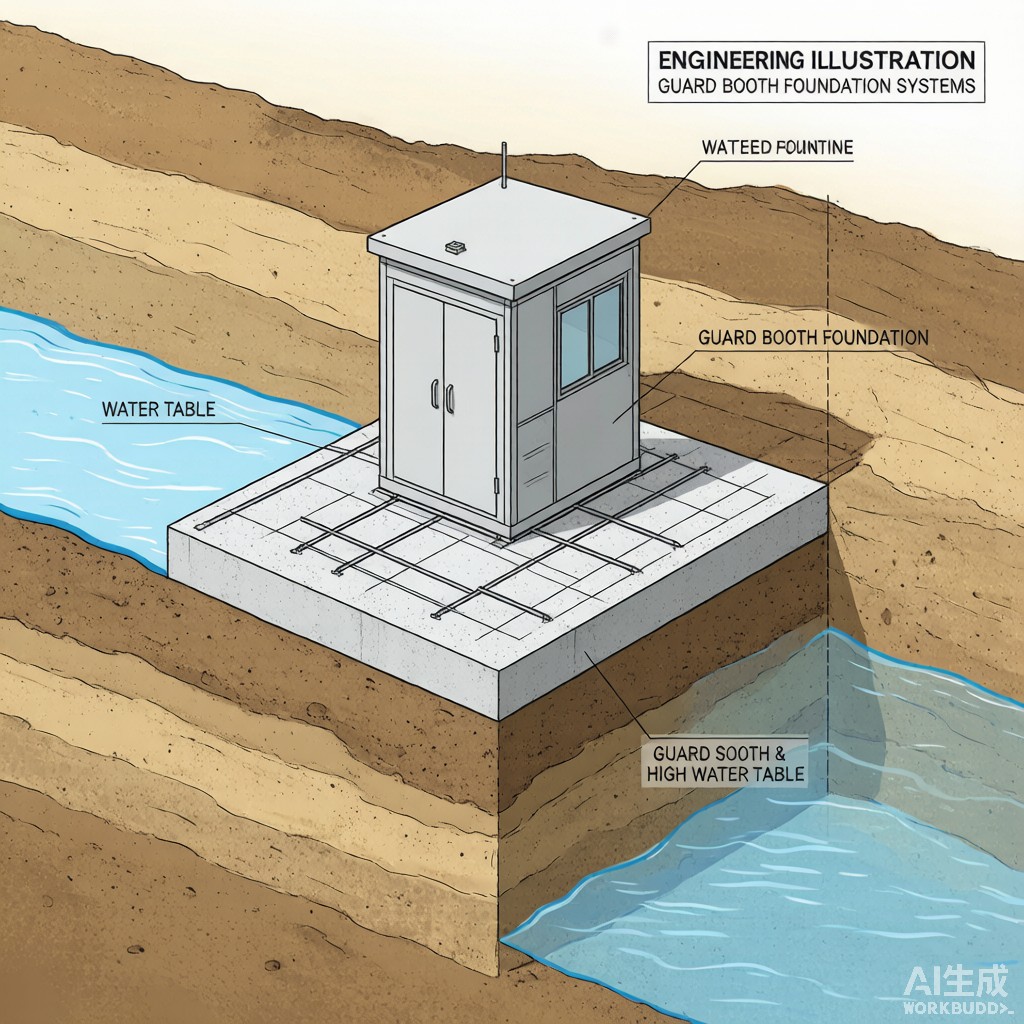
Introduction: The Foundation Challenge
Prefabricated guard booths are deployed across industrial sites, construction zones, logistics hubs, and commercial properties throughout Southeast Asia. While the booths themselves are engineered to withstand wind loads, ballistic threats, and tropical weather, their long-term performance depends entirely on the foundation beneath them. In regions with soft alluvial soils, peat deposits, and seasonally high water tables — conditions common across Vietnam, Thailand, Indonesia, and Malaysia — improper foundation design leads to differential settlement, door frame distortion, glazing failure, and utility co
ection breaks.
This article provides a systematic approach to guard booth foundation selection and design for challenging geotechnical conditions, with specific guidance for Southeast Asian site conditions.
Geotechnical Site Investigation
Minimum Investigation Requirements
Before selecting a foundation system, a geotechnical investigation must establish the soil profile, groundwater conditions, and bearing capacity at the proposed booth location. For a typical guard booth (footprint 2–4 m², dead load 1,500–3,000 kg), the minimum investigation includes:
| Investigation Item | Method | Depth | Purpose |
|---|---|---|---|
| Soil boring | SPT (Standard Penetration Test) | 5–8 m | Soil type, density, N-values |
| Groundwater monitoring | Piezometer / observation well | 3–5 m | Water table depth, seasonal variation |
| Undisturbed sampling | Shelby tube (cohesive soils) | 1–3 samples | Labor strength testing |
| Atterberg limits | Laboratory (ASTM D4318) | — | Plasticity, swell potential |
| Grain size analysis | Sieve + hydrometer (ASTM D6913) | — | Soil classification, frost susceptibility |
| Unconfined compressive strength | ASTM D2166 | — | Bearing capacity estimation |
Southeast Asian Soil Conditions
Common problematic soil types encountered at Southeast Asian industrial sites include:
| Soil Type | Typical N-value | Bearing Capacity (kPa) | Primary Risk |
|---|---|---|---|
| Soft clay (alluvial) | 2–5 | 50–100 | Consolidation settlement, low shear strength |
| Peat / organic silt | 1–3 | 20–50 | Extreme settlement, decomposition, compressibility |
| Loose sand (below water table) | 4–10 | 100–150 | Liquefaction (seismic), piping, boil |
| Fill (uncontrolled) | Variable | Unreliable | Heterogeneity, voids, debris |
| Lateritic clay (desiccated) | 15–30 | 200–300 | Shrink-swell with moisture change |
For guard booth foundations, the critical geotechnical parameters are the allowable bearing pressure at foundation depth and the expected total and differential settlement over the booth’s design life (typically 15–25 years).
Foundation System Selection
Decision Matrix
| Soil Condition | Water Table | Recommended Foundation | Typical Depth | Estimated Cost (USD) |
|---|---|---|---|---|
| Stiff clay / dense sand (N > 15) | Below footing | Isolated footing or slab-on-grade | 0.5–1.0 m | $500–1,500 |
| Medium clay (N = 5–15) | 1–2 m below surface | Reinforced mat foundation | 0.6–1.0 m | $1,500–3,500 |
| Soft clay (N = 2–5) | At or near surface | Mat + ground improvement or short piles | 1.5–4.0 m | $3,500–8,000 |
| Peat / organic soil | At surface | End-bearing piles (timber/concrete) | 4–8 m (to bearing stratum) | $5,000–12,000 |
| Loose sand (liquefiable) | At surface | Densification + mat or micro-piles | 2–5 m | $4,000–10,000 |
Mat Foundation Design for Soft Clay
Bearing Capacity Verification
For a guard booth with dimensions 1.5 m × 1.5 m and total dead + live load of 25 kN (2,500 kg), the contact pressure on a 2.0 m × 2.0 m mat foundation is:
q = P / A = 25 kN / 4.0 m² = 6.25 kPa
This is well below the allowable bearing capacity of even soft clay (50–100 kPa), suggesting that bearing capacity failure is unlikely. However, the governing design criterion for soft clay is not bearing capacity but settlement.
Settlement Analysis
Total settlement (S_total) on soft clay comprises immediate settlement (S_i) and consolidation settlement (S_c):
| Parameter | Value | Notes |
|---|---|---|
| Load (q) | 6.25 kPa | Contact pressure |
| Clay thickness (H) | 4.0 m | Below foundation to stiff layer |
| Compression ratio (Cc) | 0.35 | Typical soft alluvial clay |
| Initial void ratio (e₀) | 1.2 | Soft clay |
| Overburden pressure (σ’v0) | 25 kPa | At mid-layer (2 m depth) |
| Δσ | 5.0 kPa | Stress increase at mid-layer (Boussinesq) |
| S_c = Cc × H / (1+e₀) × log((σ’v0+Δσ)/σ’v0) | 20 mm | Primary consolidation settlement |
| S_i (elastic, immediate) | 5 mm | Occurs during construction |
| S_total | 25 mm | Over 6–18 months |
For guard booths, total settlement of 25 mm is generally acceptable if it occurs uniformly. However, if the booth is positioned near a building or pavement edge, differential settlement (typically 50–75% of total settlement) can cause tilting. A tilt of 1:200 (0.5%) is the recommended limit for guard booths — beyond this, doors may bind and glazing may crack. For 25 mm total settlement, the differential component (12–18 mm) over a 1.5 m booth width produces a tilt of 1:83–1:125, which exceeds the recommended limit.
Mitigation: Mat Foundation with Ground Improvement
When settlement analysis indicates unacceptable differential movement, ground improvement techniques reduce settlement to acceptable levels:
- Soil replacement: Excavate soft soil to 1.5–2.0 m depth, replace with compacted crushed stone or lean concrete. Reduces S_total to 5–10 mm. Cost: $200–400/m³.
- Geotextile reinforcement: Place high-strength geotextile (200 kN/m tensile strength) at the excavation base before backfill. Distributes load over wider area, reducing Δσ by 30–40%. Cost: $30–60/m².
- Rigid inclusions: Install 150–200 mm diameter concrete columns at 1.0–1.5 m spacing through the soft layer to the bearing stratum. Transfers load bypassing soft soil. Cost: $150–300/column.
Buoyancy Calculation for High Water Table Sites
When the groundwater table is at or above the foundation base, hydrostatic uplift must be evaluated. The upward buoyant force on a 2.0 m × 2.0 m × 0.3 m mat foundation is:
F_buoyancy = ρ_water × g × V_displaced = 1,000 kg/m³ × 9.81 m/s² × (2.0 × 2.0 × 0.3) m³ = 11,772 N (11.8 kN)
The resisting downward force from the booth dead load + foundation weight is approximately 30 kN. The safety factor against flotation is:
FS = F_downward / F_buoyancy = 30 / 11.8 = 2.54
A factor of safety ≥ 1.5 is required. The calculated FS of 2.54 is adequate, but if the booth is lightweight (aluminum construction, < 1,000 kg) and the foundation is thin (0.15 m slab), the FS may drop below 1.0, requiring:
- Thickened foundation slab (increase V and weight)
- Tension anchors (rock bolts or soil nails) into bearing stratum
- Extension of foundation below frost/scour depth with keyed perimeter
Construction Specifications
Concrete and Reinforcement
For tropical environments with high groundwater chloride content (common in coastal Southeast Asia), foundation concrete must resist chloride-induced corrosion:
| Parameter | Specification | Standard |
|---|---|---|
| Concrete strength (f’c) | 25–30 MPa at 28 days | ACI 318 |
| Minimum cement content | 350 kg/m³ | ACI 318 (exposure class F1) |
| Water-cement ratio | ≤ 0.45 | ACI 318 |
| Slump | 75–125 mm | ASTM C143 |
| Air content | Non-air-entrained (tropical climate) | — |
| Reinforcement | Grade 60 deformed bars (#4 @ 200 mm EW, top and bottom) | ASTM A615 |
| Concrete cover | 75 mm (against earth); 50 mm (formed surface) | ACI 318 |
| Curing | 7 days moist cure or curing compound | ACI 308 |
Anchorage Detail
The guard booth must be positively anchored to the foundation to resist wind uplift (particularly during typhoons) and seismic lateral forces. Common anchorage methods include:
- Cast-in-place anchor bolts: 4–8 bolts (M16, galvanized), embedded 300 mm into concrete with washer plates. Bolt pattern matches booth base frame.
- Adhesive anchors (post-installed): Used when foundation is pre-existing. Hilti HIT-RE 500 or equivalent epoxy adhesive, M16 threaded rod, 125 mm embedment.
- Welded co
ection:
Booth base frame welded to embedded steel plate (200 × 200 × 10 mm) in concrete. Provides highest rigidity but prevents removal.
Drainage Considerations
Foundation performance on soft soil is highly sensitive to water management. Surface water infiltration softens clay and increases settlement. Recommended drainage features include:
- Perimeter French drain (200 mm perforated PVC in crushed stone, wrapped in geotextile) at 0.5 m from foundation edge
- Surface grading: minimum 2% slope away from booth in all directions, extending 1.5 m minimum
- Downspout discharge: directed to drain, not allowed to pool near foundation
- Foundation drain (if below water table): 100 mm perforated pipe under mat, co
ected to sump pump
Conclusion
Guard booth foundation design for soft soil and high water table sites requires a systematic approach: thorough geotechnical investigation, appropriate foundation type selection, settlement analysis with mitigation measures, buoyancy verification, and corrosion-resistant construction specifications. For Southeast Asian installations where soft alluvial soils and monsoon-driven water table fluctuations are common, investing in proper foundation engineering — representing 15–25% of total booth installation cost — prevents costly structural failures, door and glazing damage, and premature booth replacement. The result is a stable, level, and durable installation that maintains operational integrity throughout the booth’s 15–25 year service life.



