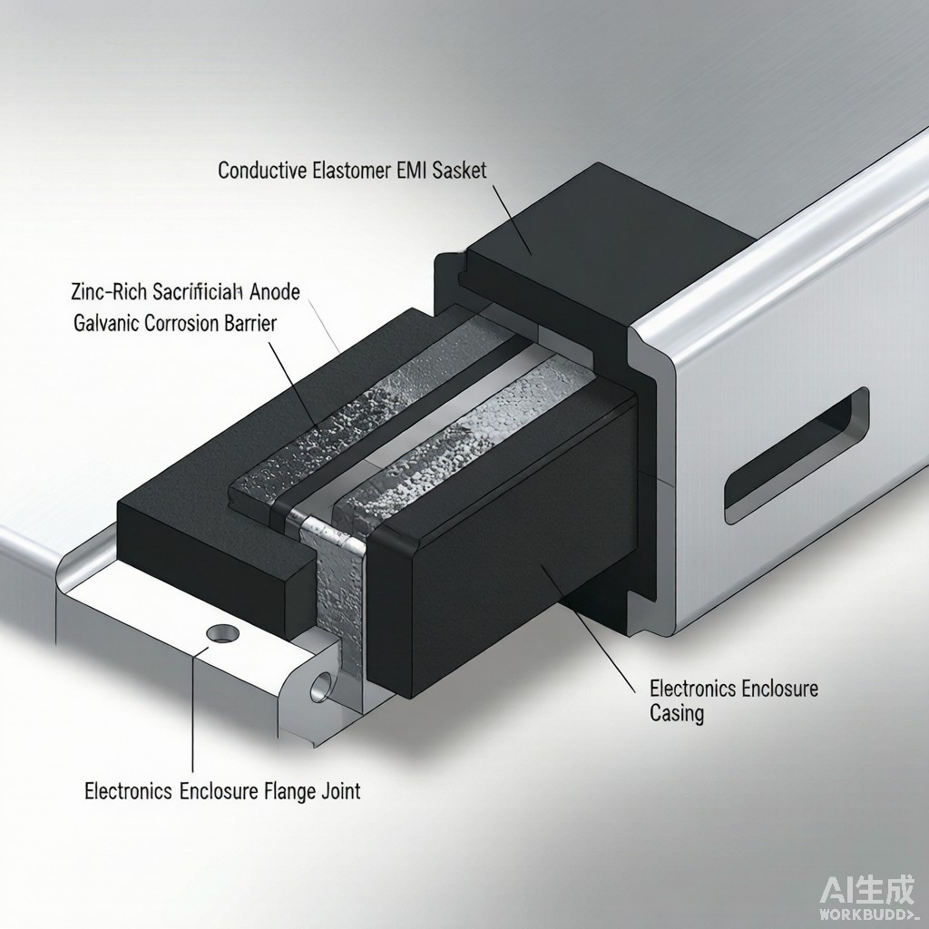
Modern electronics enclosures for 5G base stations, electric vehicle power electronics, and outdoor IoT gateways are increasingly fabricated from aluminum and magnesium alloys to reduce weight and improve thermal conductivity. When an aluminum enclosure flange is mated with an EMI gasket containing silver, nickel, copper, or tin fillers, a galvanic couple forms at the contact interface that can cause rapid corrosion in humid tropical environments. The corrosion products are typically non-conductive metal oxides that interrupt the electrical path, increase contact resistance, and degrade shielding effectiveness by 30-60 dB over 6-18 months of field exposure. This article covers the galvanic series position of common EMI gasket fillers, bimetallic couple risk assessment, mitigation strategies including barrier plating and sealing washers, and qualification testing per ASTM G82 and ISO 9227.
Galvanic Series and Bimetallic Couple Prediction
Position of Common EMI Filler Materials
The galvanic series ranks metals by their electrochemical potential in seawater. Metals near the top (noble end) such as silver (+0.15 V vs SHE), gold (+0.16 V), and copper (+0.06 V) act as cathodes and remain unattacked. Metals near the bottom (active end) such as magnesium (-1.45 V), zinc (-0.76 V), and aluminum (-0.53 V in neutral chloride solution) act as anodes and corrode preferentially. The voltage difference between the two metals predicts the driving force for galvanic corrosion, but the actual corrosion rate depends on the area ratio, electrolyte conductivity, and polarization behavior.
Common Gasket-to-Enclosure Couples
| Gasket Filler | Enclosure Material | Voltage (V) | Galvanic Risk (Tropical) | Mitigation Required |
|---|---|---|---|---|
| Silver-aluminum / silicone | Aluminum 6061-T6 | 0.65 | Very high | Tin plating + sealing washer |
| Nickel-graphite / silicone | Aluminum 6061-T6 | 0.20 | Moderate | Conductive sealant |
| Silver-copper / silicone | Aluminum 6061-T6 | 0.60 | High | Tin plating + sealing washer |
| Be-Cu finger strip | Aluminum 6061-T6 | 0.55 | High | Tin plating on finger |
| Tin-plated steel wire | Aluminum 6061-T6 | 0.25 | Low-moderate | Conductive sealant optional |
| Silver-aluminum / silicone | Magnesium AZ91D | 1.50 | Severe | Insulator + gasket only |
Galvanic Corrosion Mechanism at the Interface
Three Conditions Required for Corrosion
Galvanic corrosion requires three simultaneous conditions: two electrically co
ected dissimilar metals, an electrolyte path between them, and a driving force from the potential difference. The electrolyte in tropical electronics enclosures is typically a thin water film that forms on the flange surface when the enclosure cools below the dew point, condensing moisture from the warm interior air. This film is enriched with chloride from airborne salts, sulfur dioxide from industrial pollution, and carbon dioxide producing carbonic acid, giving a typical pH of 4.5-5.5 and conductivity of 200-1,000 µS/cm. Under these conditions, even a small cathode-to-anode area ratio of 5:1 can drive aluminum corrosion rates of 0.2-0.5 mm/year at the gasket-flange interface.
Failure Signature and Detection
Galvanic corrosion at an EMI gasket interface typically presents as a white, fluffy aluminum hydroxide or aluminum oxide deposit surrounding the gasket footprint, often accompanied by darkening or pitting of the gasket contact surface and a measurable increase in DC contact resistance from 5-20 mΩ to 200-2,000 mΩ over 6-12 months. In severe cases, the gasket separates from the flange due to the volume expansion of corrosion products, breaking the electrical bond and reducing shielding effectiveness by 40-80 dB at frequencies above 1 GHz.
Mitigation Strategies
Barrier Platings on Gasket Contact Surface
The most reliable approach is to plate the gasket contact surface or the enclosure flange with a metal that is closer in galvanic series to the mating material. Tin plating (0.005-0.015 mm) on the aluminum flange brings the surface potential to approximately -0.40 V, reducing the voltage differential to a silver-aluminum gasket to 0.50 V and the corrosion rate by a factor of 5-8. Tin is preferred over zinc because tin dissolves sacrificially but at a slower rate than zinc, and because tin’s oxide is moderately conductive (SnO₂ sheet resistance 10-100 kΩ/sq) which preserves shielding performance even after surface oxidation. For military and aerospace applications, electroless nickel (5-15 µm) over aluminum provides both wear resistance and corrosion protection, though at higher cost.
Sealing Washers and Conductive Sealants
Sealing washers made of silicone or EPDM with a captive stainless steel or tin-plated brass insert provide a physical barrier between the gasket and the aluminum flange. The washer is compressed during assembly and prevents water film formation in the gasket contact zone. Conductive sealants such as nickel-filled or silver-filled silicone caulk applied at 0.2-0.5 mm thickness around the gasket footprint provide both environmental sealing and electrical continuity, with the additional benefit of filling micro-gaps that would otherwise trap moisture.
Area Ratio Engineering
When the cathode (gasket filler) area is much smaller than the anode (aluminum flange), the corrosion current density on the small cathode is high but the total corrosion damage is small and spread over a large anode area. Conversely, when the cathode area is large (such as a silver-aluminum gasket with high filler loading covering a wide flange strip), the anode is driven at high current density and pitting can perforate the flange within 1-2 years. Design rules for limiting this risk specify a cathode-to-anode area ratio not exceeding 1:10, achieved by reducing gasket width to 1.5-2.5 mm or by using nickel-graphite filler with area ratio up to 1:3.
Qualification Testing per ASTM G82 and ISO 9227
Galvanic compatibility of new gasket-enclosure couples should be verified through ASTM G82 cyclic galvanic corrosion testing or ISO 9227 salt spray testing for 500-1,000 hours. Acceptance criteria include: (1) DC contact resistance change less than 50 mΩ from initial value; (2) shielding effectiveness at 1 GHz within 5 dB of initial value; (3) no visible pitting deeper than 0.05 mm on the aluminum flange; (4) gasket compression set less than 15% after environmental exposure. Field validation in target tropical climates for 6-12 months is also recommended because laboratory accelerated tests sometimes under-predict corrosion rates at the gasket-flange interface due to complex geometry effects.
When properly engineered, the combination of barrier plating, sealing washer, and controlled area ratio allows silver-aluminum gaskets to be safely deployed on aluminum enclosures in coastal 5G base station and EV charging station applications for 15-20 year service life with no measurable galvanic degradation.



