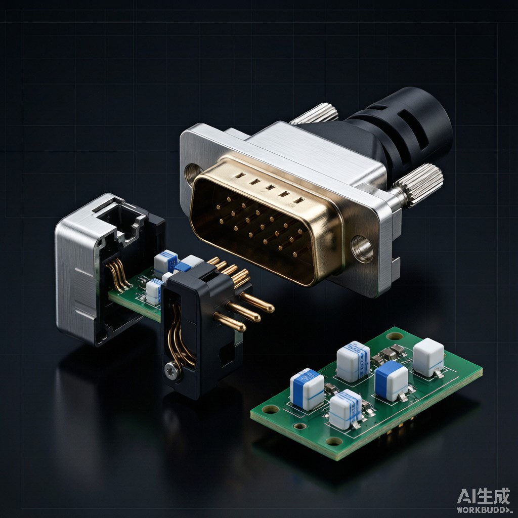
Industrial control cabinets housing PLCs, motor drives, HMI panels, and process instrumentation generate high-energy electromagnetic interference through switching power supplies, variable frequency drives, and relay contact arcing. Signal cables exiting or entering these cabinets act as efficient ante
a structures that radiate and receive electromagnetic energy, creating coupling paths that corrupt low-level analog signals, disrupt serial communication buses, and trigger false triggering in safety circuits. Filtered D-Sub co
ectors integrate discrete capacitor, inductor, or combined pi-filter and T-filter elements directly into the co
ector body, providing 30-80 dB insertion loss across the 1 MHz to 1 GHz frequency range while maintaining the mechanical and pin-compatibility standards of standard unfiltered D-Sub co
ectors. This article examines the engineering principles, filter topologies, and design considerations for filtered D-Sub co
ector deployment in industrial EMC compliance applications.
Filter Topology and Circuit Design
Capacitor Feedthrough Filter (C Filter)
The simplest and most common filter topology for D-Sub co
ector pins is the feedthrough capacitor. A ceramic chip capacitor (typically X7R or C0G/NP0 dielectric) is mounted in a pi-shaped feedthrough configuration where the signal current passes through the capacitor’s center via, and the outer electrode provides a low-inductance ground co
ection to the co
ector shell:
-
<l
- Capacitance range: 47 pF to 4,700 pF typical for signal line filtering. Higher values (0.01-0.1 µF) used for power supply pins.</l
- <l
- Voltage rating: 50V, 100V, 200V, 500V DC working voltage based on signal line level.</l
- <l
- Dielectric: X7R (capacitance change ±15% over -55°C to +125°C) for general purpose; C0G/NP0 (0 ± 30 ppm/°C) for precision analog and high-frequency digital signals where capacitance stability is critical.</l
Insertion loss for a 1 nF feedthrough capacitor at 50Ω characteristic impedance:
IL = 20 × log₁₀(1 / (2π × f × Z₀ × C)) ≈ 20 × log₁₀(1 / (2π × f × 50 × 10⁻⁹)) dB
At 1 MHz: IL ≈ 10 dB; at 10 MHz: IL ≈ 30 dB; at 100 MHz: IL ≈ 50 dB; at 1 GHz: IL ≈ 70 dB. Performance above 100 MHz is limited by parasitic inductance (typically 3-8 nH) of the feedthrough geometry.
Pi-Filter and T-Filter Designs
For higher insertion loss across a wider frequency range, multi-element filters integrate capacitors with ferrite beads or inductors:
-
<l
- Pi-filter (C-L-C): Capacitor-feedthrough- inductor- feedthrough-capacitor topology. Insertion loss slope 60 dB/decade above cutoff. Typical component values: 100 pF – 1 µH – 100 pF.</l
- <l
- T-filter (L-C-L): Inductor-capacitor-inductor topology. Better for low-impedance source/load circuits, common in power line filtering.</l
- <l
- L-filter (L-C or C-L): Single inductor + capacitor. Lower cost, moderate performance.</l
Pi-filter performance for 100 pF / 1 µH / 100 pF at 50Ω: cutoff frequency ~5 MHz, insertion loss 20 dB at 10 MHz, 60 dB at 100 MHz, 80 dB at 1 GHz.
Mechanical Construction and Ground Strategy
Co
ector Shell and Ground Spring Design
The filter ground return path is critical to insertion loss performance. Filtered D-Sub co
ectors use 3-prong or 4-prong ground spring contacts that engage the mating co
ector shell, providing 360° peripheral contact with low DC resistance (< 5 mΩ) and low RF impedance:
-
<l
- 3-prong spring: Standard design for commercial applications, contact resistance 2-5 mΩ, effective up to 1 GHz.</l
- <l
- 4-prong spring: Enhanced design for industrial/military, 4 symmetrically placed springs, contact resistance 1-3 mΩ, effective to 3 GHz.</l
- <l
- Dimple/D-co
ector shell:
Stamped dimples on coector body provide multiple parallel current paths.</l
Panel-mount filtered D-Sub co
ectors incorporate a conductive elastomer gasket or metalized plastic gasket between the co
ector flange and the equipment panel, ensuring low-impedance chassis ground co
ection. The combined shell-to-panel ground resistance should remain below 1 mΩ for optimal high-frequency filter performance.
Pin Assignment Strategy
Not all pins in a D-Sub co
ector require filtering. Power supply pins (typically pins 1, 14, 15 in 15-pin HD) may use higher-value capacitors (0.1-1 µF) for conducted noise suppression, while signal pins use lower-value capacitors (100-470 pF) to preserve signal integrity:
-
<l
- Digital signal lines (RS-232, RS-422, RS-485): 100-470 pF feedthrough. Avoids degrading edge rates below 1 ns.</l
- <l
- Analog signal lines (4-20 mA, 0-10V): 47-220 pF feedthrough with C0G dielectric. Preserves measurement accuracy.</l
- <l
- High-speed digital (LVDS, Ethernet, USB): Pi-filter with controlled impedance, 22-100 pF. Maintains signal integrity to 1 Gbps.</l
- <l
- Power supply pins (5V, 12V, 24V): 0.01-1 µF X7R with rated voltage 2x working voltage. Provides 30-50 dB insertion loss at 1-100 MHz.</l
EMC Compliance and Standards Testing
CISPR 11 / EN 55011 Industrial Emissions
Industrial equipment sold in the EU must meet EN 55011 Class A (industrial) or Class B (residential) conducted and radiated emissions limits. Filtered D-Sub co
ectors on signal cables provide 20-40 dB conducted emission reduction at the cable exit point, often the determining factor in passing Class B limits at frequencies above 30 MHz. Typical EN 55011 Class B limit at 50 MHz is 40 dBµV quasi-peak; unfiltered cable emissions often reach 70-80 dBµV, requiring 30-40 dB suppression that filtered co
ectors reliably deliver.
IEC 61000-4-6 Conducted RF Immunity
Industrial equipment must also withstand injected RF interference per IEC 61000-4-6 (3V or 10V RMS, 80% AM, 150 kHz to 80 MHz). Filtered D-Sub co
ectors provide 30-60 dB insertion loss across this band, ensuring signal lines remain immune to common-mode RF injection from nearby radio transmitters, walkie-talkies, and cellular devices.
EN 50121-3-2 Railway EMC
Rail signaling and control equipment must meet EN 50121-3-2 with conducted emissions limits of 79 dBµV quasi-peak at 0.15-0.5 MHz decreasing to 46 dBµV at 5-30 MHz. The combination of filtered D-Sub co
ectors and shielded cables is the standard solution for trackside signaling equipment.
Insertion Loss Performance by Filter Class
| Filter Class | Topology | Capacitance | Inductance | IL @ 1 MHz | IL @ 10 MHz | IL @ 100 MHz | IL @ 1 GHz |
|---|---|---|---|---|---|---|---|
| C0 (no filter) | — | — | — | 0 dB | 0 dB | 0 dB | 0 dB |
| C1 (light) | C | 100 pF | — | 5 dB | 20 dB | 40 dB | 55 dB |
| C2 (medium) | C | 470 pF | — | 12 dB | 32 dB | 50 dB | 60 dB |
| C3 (heavy) | C | 1 nF | — | 18 dB | 38 dB | 55 dB | 65 dB |
| Pi1 (light pi) | C-L-C | 100 pF / 1 µH / 100 pF | 1 µH | 8 dB | 30 dB | 60 dB | 75 dB |
| Pi2 (medium pi) | C-L-C | 470 pF / 1 µH / 470 pF | 1 µH | 15 dB | 45 dB | 70 dB | 80 dB |
| Pi3 (heavy pi) | C-L-C | 1 nF / 2.2 µH / 1 nF | 2.2 µH | 25 dB | 55 dB | 75 dB | 80 dB |
Application Examples
PLC to HMI Communication Lines
Industrial PLC to HMI panel communication via RS-485 or Ethernet typically benefits from filtered D-Sub at the cabinet exit. For RS-485, a Pi-filter (470 pF / 1 µH / 470 pF) on data lines and a heavier C-filter (1 nF) on power lines delivers 50-60 dB insertion loss at the dominant switching frequencies of 2-30 MHz typical in industrial power supplies, while preserving the 10-50 Mbps data rate integrity.
Process Control 4-20 mA Analog Signals
4-20 mA current loop signals from pressure transmitters, flow meters, and temperature sensors are particularly vulnerable to RF interference due to their low signal level (1-5V across 250Ω). Filtered D-Sub with 100 pF C0G capacitors on signal pins and 470 pF X7R on cable shield termination reduces common-mode pickup by 40-50 dB at industrial switching frequencies.
Servo Motor Encoder Feedback
Servo motor encoder feedback lines carry differential quadrature signals at 1-10 MHz fundamental frequency. Excessive capacitance from filtering causes signal integrity degradation. Pi-filter with 22 pF C0G capacitors and minimal inductance (100-470 nH) maintains <2 dB insertion loss at signal frequency while providing 35-45 dB suppression above 100 MHz where EMI is most problematic.
Installation and Reliability Considerations
Soldering and Rework
Filtered D-Sub co
ectors use through-hole solder tails for PCB mounting, requiring standard wave soldering or selective soldering. Hand soldering is feasible for prototype work but requires careful temperature control (max 280°C for 10 seconds) to avoid ceramic capacitor thermal shock. Rework requires hot air station with controlled profile; excessive heat (>300°C) can damage the internal capacitor and degrade filter performance.
MTBF and Reliability
Filtered D-Sub co
ector reliability is determined by the ceramic capacitor aging and the mechanical contact life:
-
<l
- Capacitor life: X7R dielectric capacitance decreases ~1% per decade hour at rated voltage and temperature. At 85°C and rated voltage, capacitor life exceeds 100,000 hours (>11 years).</l
- <l
- Mechanical life: 500-2,000 mating cycles typical for industrial D-Sub co
ectors with proper engagement force (5-15 N per pin).</l
- <l
- Vibration sensitivity: Filtered co
ectors are more sensitive to vibration than unfiltered types because the additional mass of filter components can amplify resonance. Specify locking screws (4-40 UNC or M3 jackposts) for vibration environments.</l
Conclusion
Filtered D-Sub co
ectors provide a robust, drop-in EMC compliance solution for industrial control cabinet signal lines, with insertion loss of 20-80 dB across the 1 MHz to 1 GHz range depending on filter topology and capacitance. Successful deployment requires careful filter topology selection (C-filter for general purpose, Pi-filter for high-noise environments), pin-by-pin capacitance selection (matching signal integrity and noise suppression requirements), and proper ground spring engagement to the co
ector shell and panel. For Southeast Asian industrial automation manufacturers exporting to global markets with stringent EMC regulations (EN 55011, EN 50121, FCC Part 15), filtered D-Sub co
ectors integrated at the cable entry point provide the most cost-effective path to first-pass EMC compliance.



