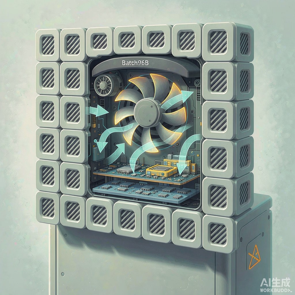
Every electronics engineer eventually meets the same problem: the prototype works, but in a sealed enclosure the board cooks. Natural convection has limits — roughly 15–25 W for a well-vented desktop enclosure — and beyond that, forced air is the practical answer. The catch is that fan selection is not just “pick a CFM number.” This guide walks through the thermal budget, the fan curve versus system impedance, and the layout decisions that decide whether your enclosure actually stays cool.
Start With a Thermal Budget
First decide how much temperature rise you can tolerate. If the ambient inside your cabinet can reach 45°C and your components need to stay below 85°C junction temperature, you have some margin — but the air temperature rise from inlet to outlet is what the fan controls. The required airflow follows from a simple energy balance:
Q (CFM) ≈ 3.16 × P (W) / ΔT (°C)
Example: 200 W of dissipation with an allowable 10°C air rise needs about 63 CFM of air actually flowing through the box. With a 20°C rise allowance, only 32 CFM is needed. The ΔT you grant yourself is the single biggest lever in fan sizing.
The Classic Rules of Thumb, Corrected
Old rulebooks quote “1 CFM per watt” for open racks. In enclosed equipment with filtered vents and hot spot concentration, plan for 0.4–0.7 CFM/W as a starting point, then verify with measurement. Derate for altitude — air density, and therefore cooling effectiveness, drops about 10% per 1000 m above sea level.
System Impedance and the Operating Point
The CFM printed on a fan box is free air flow: zero backpressure. Your enclosure is not free air. Every filter, vent grille, PCB stack, and cable bundle adds resistance, described by a system impedance curve that follows the square law — double the flow, quadruple the pressure drop.
The real operating point is where the fan’s P-Q curve intersects your system impedance curve. Dense boards with tight cha
el spacing create steep (high-impedance) curves, and a fan chosen by free-air CFM alone may deliver half its rated flow once installed. Two practical implications:
- In high-impedance systems (dense SMT boards, EMI honeycomb vents, dust filters), choose a fan with high static pressure — usually a smaller diameter fan at higher speed, or a blower.
- In low-impedance systems (open racks, widely spaced boards), a large, slow axial fan moves more air at lower noise and longer life.
Axial Fans vs Blowers
| Type | Best For | Watch Out For |
|---|---|---|
| Axial fan | Low-to-medium impedance, high flow, front-to-back cabinet cooling | Poor in tightly stacked boards; flow drops sharply with backpressure |
| Centrifugal blower | High impedance, concentrated heat sources, 1U/2U chassis | Higher noise and power; shorter bearing life at high speed |
| Mixed flow | Compromise between flow and pressure | Fewer standard sizes available |
Derating and Life: What the Datasheet Hides
Rated airflow is measured at 25°C with no obstruction. Inside a warm enclosure, both flow and bearing life degrade. Check these specifications before committing:
- Bearing type: sleeve bearings are cheap but dry out above 40–50°C; ball bearings or dual-ball designs hold L10 life above 50,000 hours at 60°C.
- L10 life at operating temperature, not at 25°C. A fan rated 70,000 h at 25°C may be 30,000 h at 60°C.
- PWM or voltage control: variable-speed fans cut noise and extend life by idling when load is light — and give you a speed-error signal for predictive maintenance.
- IP rating and filters: outdoor telecom cabinets need IP54/IP55 fans plus washable filters; budget the filter pressure drop into your impedance curve, and re-check it when filters load with dust.
Layout Rules That Decide the Outcome
- Push or pull? Pushing air through the enclosure slightly raises internal pressure and keeps dust out through gaps; pulling lowers pressure and drags dust in through every leak. For dusty sites, push.
- Separate inlet from outlet. Vents too close create recirculation loops where hot exhaust re-enters the inlet — the most common field mistake. Aim for diagonal placement and internal baffles.
- Match vent area to fan. A fan starved by a small inlet grille just makes noise. Total open vent area should be at least 80% of the fan’s active area, preferably more.
- Cool the hot spot first. Direct airflow across the highest-dissipation components (power supplies, drive stages) rather than hoping bulk flow finds them.
- Keep cables out of the flow path. A cable bundle across the fan outlet can cost 10–20% of flow.
Verify With Measurement, Not Guesswork
Once assembled, measure inlet and outlet air temperature with the boards ru
ing at worst-case load. Outlet-minus-inlet temperature should match your design ΔT; if the rise is larger, either flow is lower than expected (check impedance, filters, leaks) or dissipation is higher than modeled. An anemometer at the outlet confirms actual CFM within about 10%.
Key Takeaways
Fan selection is a system problem: thermal budget first, then impedance-matched fan choice, then layout, then measurement. A fan that delivers half its rated flow in a high-impedance stack is the norm, not the exception — so design margins into the airflow estimate, prefer pressure-capable fans for dense boards, and use PWM control to buy life and quiet operation.



