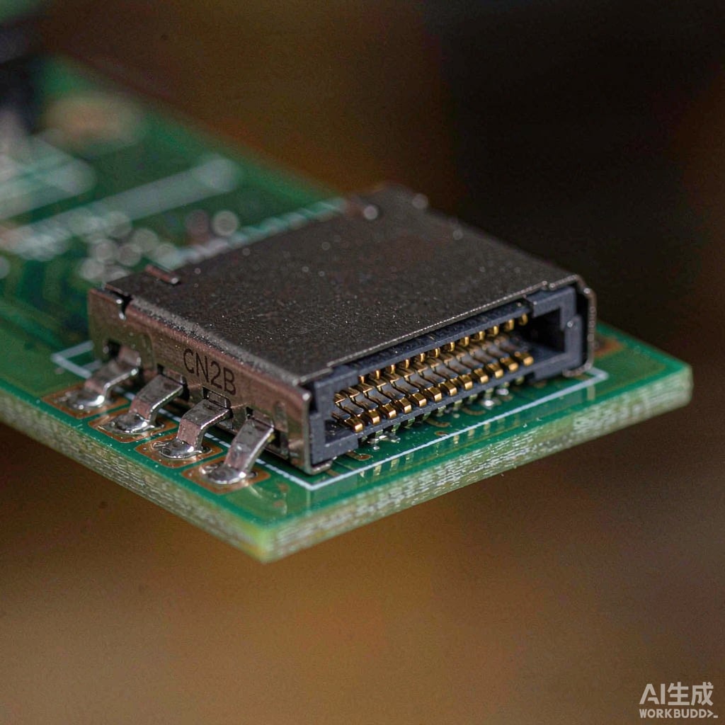
The Co
ector Is the Ante
a’s Front Door
When a product with USB 3.x, DisplayPort Alt Mode, or 10 GbE fails EMC testing, the radiation almost never comes from the chips – it comes from the co
ector and the cable attached to it. High-speed serial signals have edge rates fast enough that even small asymmetries convert differential energy into common-mode noise, and the cable becomes an efficient ante
a at hundreds of megahertz to several gigahertz. The co
ector shell is where the differential world inside the product meets the common-mode world outside it, which makes co
ector shielding design one of the highest-leverage EMI decisions in the whole product.
Where Common-Mode Noise Comes From
Three conversion mechanisms dominate:
- Skew between differential pairs: a few picoseconds of length mismatch converts a slice of the differential signal into common-mode. At 10 Gbps, 5 ps of skew is meaningful.
- Reference-plane discontinuities: when the fast signal crosses a via or a gap in the ground plane, return current detours and the loop area radiates.
- Poor shell bonding: if the co
ector shell co
ects to chassis ground through a high-impedance path (thin trace, pigtail, or none at all), noise injected onto the shell has nowhere to go except onto the cable.
Shell Grounding: The Rules That Matter
360-Degree Bond at the Bulkhead
The co
ector shell should bond to the chassis or shield plane around its full circumference. USB-C receptacles have solder tabs for this purpose; use all of them, not just the signal-side ground pins. A full-periphery bond keeps shell impedance low across the frequency range where the cable radiates.
No Pigtails, Ever
A 20 mm wire from shell to ground is an inductor of roughly 20-30 nH – by 500 MHz that is hundreds of ohms, meaning the shell is effectively floating at exactly the frequencies you care about. This single error explains a large share of consumer-product EMC failures.
Decide the Topology Deliberately
In grounded-metal products, bond the shell directly to chassis. In plastic products with no chassis ground, the shell must tie to the PCB’s clean signal ground at multiple points near the co
ector, and the board’s ground strategy (solid plane under the co
ector, stitching vias to any secondary ground structure) carries the burden the chassis would have.
Cable Shield Termination
A well-grounded co
ector feeding a badly terminated cable still fails. In USB-C assemblies the shield is typically terminated 360 degrees to the plug shell inside the overmold – specify and verify this when sourcing cables, because cheap assemblies sometimes rely on a drain wire twisted to the shell. For board-level designs using cable assemblies with drain shields, the drain should land on a low-impedance ground pad immediately at the co
ector, with no routing.
Overmold Ferrites and Common-Mode Chokes
- Board-level common-mode chokes: placed directly at the co
ector side of the super-speed pairs, sized for the data rate (a choke for 480 Mbps USB 2.0 will destroy 10 Gbps eye margins; use parts specified to the actual standard).
- Clamp-on ferrites: a legitimate fix and a diagnostic tool – if a snap-on ferrite at the co
ector reduces the emission significantly, the noise is common-mode on the cable, which tells you exactly where to look.
Board Layout Details That Pay Off
- Keep length skew inside each high-speed pair under 0.15-0.25 mm at 10 Gbps class signals.
- Maintain a continuous, unbroken reference plane under the pairs from chip to co
ector; never route across plane splits.
- Add stitching vias along the co
ector breakout region at intervals below λ/20 of the highest concern frequency.
- Place AC coupling capacitors symmetrically in both legs of the pair so their pads do not create skew or impedance bumps.
Pre-Compliance Testing That Catches Co
ector Problems Early
You do not need a full EMC chamber to catch these failures. Three bench measurements find most cable-and-co
ector EMI problems:
- Near-field probe scan over the co
ector and the first 100 mm of cable with a ru
ing link; hot spots at the shell bond points reveal high-impedance grounding.
- Common-mode current measurement: clamp a current probe around the cable and measure the CM current spectrum; more than a few microamps at 30-300 MHz predicts a radiated failure.
- Delta test with ferrite: repeat the CM scan with a clamp ferrite installed; a large improvement confirms common-mode cable radiation as the mechanism.
Run these before the formal CISPR 32 / FCC Part 15 test, and the chamber visit becomes confirmation instead of debugging.
Sourcing Considerations
When selecting USB-C and high-speed co
ectors, prefer receptacles with multiple full ground/shell tabs and documented shell-to-tab impedance, plugs with 360-degree shield termination in the overmold, and impedance-controlled pair construction (90 ohms ±10% differential for USB 3.x). Ask suppliers for S-parameters or at minimum insertion-loss and return-loss plots to 10 GHz and beyond – a co
ector with a hidden impedance discontinuity turns into a common-mode generator no amount of downstream filtering can fix.
Conclusion
High-speed co
ector EMI is won or lost at three places: the shell bond, the cable shield termination, and the return path on the board. Bond shells 360 degrees, never use pigtails, terminate cable shields at the plug, and measure common-mode current early in development. These habits cost almost nothing at design time and save the most expensive kind of EMC debugging there is.



