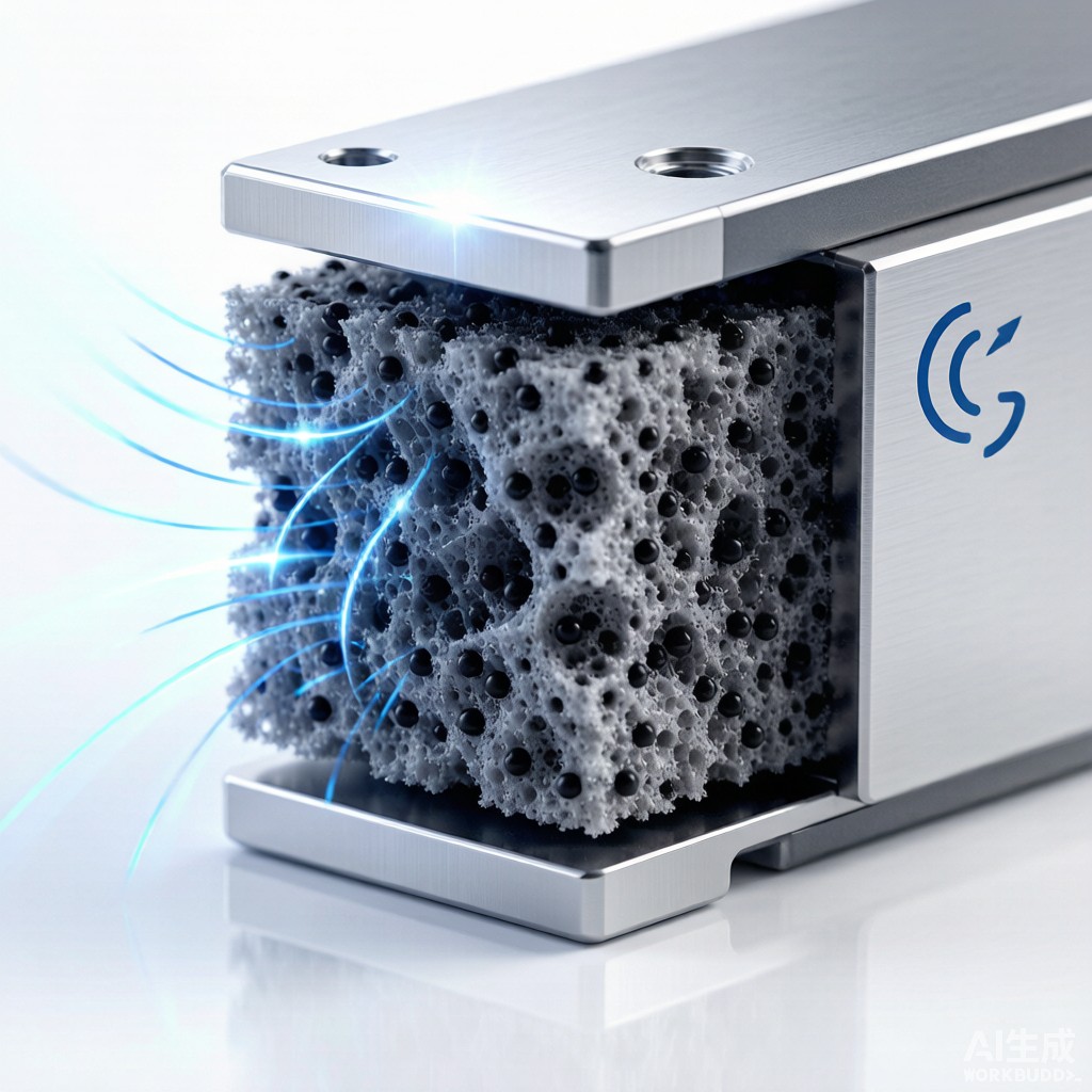
Introduction: The Hidden Failure Mode of EMI Gaskets
EMI shielding foam gaskets are used in countless electronics enclosures, from 5G base stations and medical imaging systems to industrial control panels and automotive ECUs. They provide the compliant conductive joint between a metal housing and its cover, preventing electromagnetic energy from leaking through gaps. When first installed, a quality gasket delivers 80-120 dB of shielding effectiveness. But over months and years of thermal cycling, humidity exposure and mechanical relaxation, the gasket may lose its elastic recovery — a phenomenon called compression set — and the shielding performance can degrade without any visible sign of failure.
This article examines the materials science, design rules and qualification methods that govern long-term reliability of EMI shielding foam gaskets in electronics manufacturing.
How Conductive Foam Gaskets Work
Foam Structure and Conductive Pathways
EMI shielding foam consists of an open-cell or semi-open-cell polymer foam — typically polyurethane, silicone or polyolefin — plated or loaded with electrically conductive material. Nickel-graphite plated polyurethane foam is the most common type, offering good shielding, moderate cost and wide availability. Silver-plated fabric-over-foam gaskets provide higher performance for military and medical applications.
Conductivity is created by the network of metal particles or plating that coats the foam struts. When compressed between two conductive surfaces, the particles make contact with both surfaces and with each other, forming a conductive path across the gap. The foam elastomer provides the restoring force that maintains contact pressure despite cover bowing, tolerance stack-up and thermal expansion differences.
Shielding Effectiveness Mechanisms
A gasket contributes to shielding in two ways. First, it provides electrical continuity across the seam, preventing the gap from acting as a slot ante
a. Second, it absorbs and reflects electromagnetic energy through the conductive plating. The combined effect depends on:
- Gasket thickness and compression ratio
- Conductive particle loading and plating continuity
- Contact surface finish and cleanliness
- Number of conductive contact points per unit length
Compression Set and Why It Matters
The Physics of Permanent Deformation
Compression set is the permanent deformation remaining after a gasket has been compressed and then released. A gasket with high compression set no longer springs back to its original thickness, so contact pressure drops and electrical continuity becomes intermittent. In severe cases, the gasket collapses to a thin ribbon that no longer fills the gap.
Compression set is driven by polymer chain relaxation, oxidative cross-linking and physical aging. At elevated temperatures, these processes accelerate. A polyurethane foam gasket that shows 15% compression set at room temperature may exceed 50% after 1,000 hours at 85°C — a common condition inside enclosed electronics.
Typical Compression Set Values
| Gasket Material | Room-Temp Compression Set (%) | 85°C/1,000 h Compression Set (%) | Recovery Behavior |
|---|---|---|---|
| Nickel-graphite PU foam | 10-20 | 35-55 | Moderate; suitable for consumer/industrial |
| Silicone foam | 5-10 | 15-25 | Excellent; preferred for high-temp |
| Fluorosilicone foam | 5-12 | 15-30 | Excellent; fuel/oil resistant |
| Fabric-over-foam | 15-25 | 40-60 | Fair; dependent on foam core |
For long-life products, silicone or fluorosilicone foam gaskets are usually worth the higher material cost because their compression set resistance extends enclosure shielding reliability by years.
Environmental Aging and Performance Degradation
Temperature and Humidity
High temperature accelerates polymer oxidation and compression set. Humidity promotes galvanic corrosion at the interface between dissimilar metals — for example, a nickel-graphite plated gasket against an aluminum enclosure. Corrosion products increase contact resistance and can lift the gasket away from the surface, creating an EMI leak.
For tropical electronics manufacturing and deployment in Southeast Asia, 85°C/85% relative humidity aging tests for 1,000 hours are a minimum qualification requirement. Some automotive and outdoor products require 1,500 hours or more.
Salt Spray and Chemical Exposure
Coastal installations and marine equipment expose gaskets to salt spray, which accelerates corrosion of nickel and silver platings. Fluorosilicone gaskets with passivated conductive fillers perform better in these environments. Chemical exposure from cleaning solvents, lubricants or outgassing adhesives can also swell or degrade the foam polymer, changing compression characteristics.
Gasket Groove and Compression Design
Compression Percentage
Most EMI foam gaskets are designed to operate at 20-40% compression. Below 20%, contact pressure may be too low to establish reliable particle-to-surface contact. Above 50%, compression set increases rapidly and the risk of foam collapse rises. A target of 25-35% compression balances shielding performance, longevity and tolerance absorption.
Groove Geometry
For groove-mounted gaskets, the groove depth should be selected to achieve the target compression at the nominal gasket thickness. Groove width should be 1.1-1.3 times the gasket cross-section to allow lateral expansion without binding. Sharp groove corners should be avoided; a minimum corner radius of 0.5 mm reduces stress concentration and tearing during assembly.
Qualification Test Methods
Common qualification tests for EMI shielding gaskets include:
- Shielding effectiveness: MIL-DTL-83528, IEEE 299 or ASTM D4935 over 30 MHz to 18 GHz.
- Compression set: ASTM D3574 Test D (polyurethane) or ASTM D395 (silicone).
- Environmental aging: 85°C/85% RH, thermal cycling (-40°C to +125°C), salt spray per ASTM B117.
- Compression-deflection curve: Defines force vs. compression for assembly load and long-term stress.
Qualification should be performed on gasket samples bonded with the same adhesive and against the same enclosure finish pla
ed for production. Surface finish changes — for example, switching from chromated aluminum to anodized aluminum — can significantly alter contact resistance and corrosion behavior.
Conclusion
EMI shielding foam gaskets are simple in concept but demanding in long-term reliability. Compression set, corrosion, temperature aging and improper compression design can all reduce shielding effectiveness below acceptable levels after months or years in service. Electronics manufacturers in high-reliability markets should specify silicone or fluorosilicone foam for demanding applications, design grooves for 25-35% compression and validate gaskets through environmental aging and shielding effectiveness testing before committing to production.



