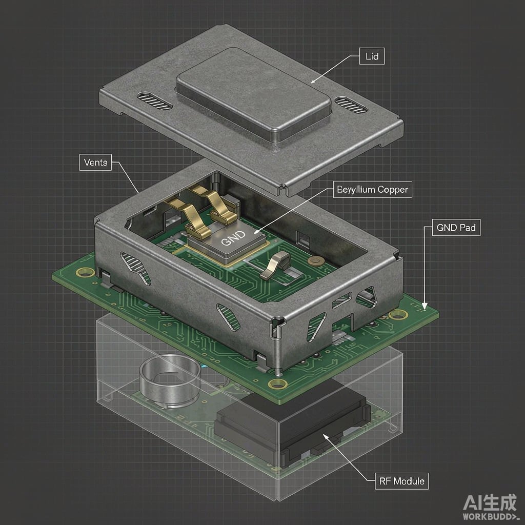
The Role of Spring Fingers in Shielding Can Grounding
Board-level EMI shielding cans protect sensitive RF circuits from external interference and prevent emissions from propagating across the PCB. A shielding can is only as effective as its grounding path to the PCB ground plane. While solder-attached cans provide a continuous low-impedance co
ection, they make rework difficult and are impractical for modular designs. Spring finger grounding contacts offer a removable, serviceable alternative that maintains reliable electrical contact under compression, vibration, and thermal cycling.
Spring fingers — also called grounding clips, shielding clips, or EMI gaskets — are small stamped metal contacts that provide a compliant bridge between the shielding can flange and a PCB ground pad. Their design involves a careful trade-off among compression force, contact resistance, cycling durability, and spatial efficiency.
Compression Force: Finding the Sweet Spot
Contact force is the primary driver of contact resistance and reliability. When two metal surfaces are pressed together, the true contact area is much smaller than the apparent area because surface asperities dominate. Higher compression force deforms these asperities, increasing the true contact area and lowering contact resistance.
For EMI shielding spring fingers, the recommended contact force per finger ranges from 0.5 N to 3.0 N, depending on the application:
| Application | Force per Finger | Contact Resistance Target |
|---|---|---|
| Consumer mobile (5G sub-6) | 0.5-1.0 N | <20 mΩ |
| Automotive radar (77 GHz) | 1.0-2.0 N | <10 mΩ |
| Military / aerospace | 2.0-3.0 N | <5 mΩ |
Below 0.3 N, contact becomes unreliable because normal oxidation and contamination films are not breached. Above 4 N, PCB pad wear and finger set (permanent deformation) become concerns, and the total force on a multi-finger can may warp the PCB.
Spring Finger Geometry and Material Selection
Common Finger Designs
- Cantilever beam: The simplest geometry, a single bend that acts as a fixed-free beam. The spring constant is k = Ebt³/(4L³) where b is width, t is thickness, and L is beam length. It offers good compliance but limited contact force per unit deflection.
- U-clip (folded beam): A U-shaped stamping with two legs. The design doubles the contact area and provides redundancy if one leg fatigues, while the geometry stabilizes lateral position.
- S-formed (multi-bend): An S-curve with multiple bends increases compliance range and allows greater deflection without yielding. Preferred for cans with larger assembly tolerance stacks.
- Belleville (washer-like): A stamped washer that provides high force in a compact axial space. Used in screw-attached can designs where a spring washer sits between the can flange and a standoff.
Material and Finish
The dominant material for spring fingers is beryllium copper (C17200) in the precipitation-hardened condition (ASTM B194, temper TH02). It offers the highest spring strength-to-conductivity ratio, with elastic modulus of 131 GPa, yield strength above 1000 MPa (after aging at 315 C for 2 hours), and electrical conductivity of 15-28% IACS. Alternatives include C70250 Corson alloy (lower cost, conductivity 25-40% IACS, but lower yield strength) and stainless steel 301 (excellent corrosion resistance but conductivity below 3% IACS, requiring a conductive plating).
Plating options include:
- Gold over nickel: 0.05-0.1 micrometers Au over 1-2 micrometers Ni. Best corrosion resistance and lowest contact resistance (1-5 mΩ). Standard for automotive and military.
- Tin over nickel: 1-3 micrometers Sn over 0.5-1 micrometers Ni. Economical and solder-compatible, but tin whisker risk must be managed (mitigated by matte tin or reflowed tin).
- Silver over copper: 0.2-0.5 micrometers Ag. Excellent conductivity for RF, but tarnishes in sulfur-containing environments.
Cycling Durability and Relaxation
In serviceable modules, the shielding can may be removed and reinstalled multiple times. Each cycle plastically deforms the contact asperities and can reduce contact force through stress relaxation. Beryllium copper fingers typically maintain adequate force for 20-50 reassembly cycles; Corson alloy for 10-20 cycles. Operating temperature also affects performance: at 85 C, stress relaxation of Be-Cu after 1000 hours is approximately 5-8%, compared to 15-25% for phosphor bronze.
Vibration introduces a separate failure mode: fretting wear at the contact interface. Hard gold plating reduces fretting damage, while soft tin plating is more susceptible. For automotive and aerospace applications, designers often specify a minimum of 3-4 fingers per can edge to provide redundancy against individual finger degradation.
Shielding Effectiveness and Grounding Path Inductance
The shielding effectiveness of a grounded can depends not only on the can material and apertures but also on the impedance of the grounding path. Each spring finger contributes a small series inductance. For a row of N fingers spaced at pitch p along an edge of length L, the distributed inductance per unit length is approximately L_d = L_finger/(N x p), where L_finger is the self-inductance of each finger and its via-to-ground path (typically 1-5 nH). At 10 GHz, an inductance of 1 nH represents an impedance of about 63 ohms, which is comparable to free-space impedance and can degrade shielding by 10-20 dB if insufficient fingers are used.
The guideline is to place grounding fingers at intervals no greater than lambda/20 of the highest frequency of concern. For a 10 GHz signal, lambda/20 in FR-4 is approximately 0.75 mm, meaning a contact every 0.75 mm along the perimeter. In practice, designers use continuous gaskets or closely spaced fingers for high-frequency shielding and discrete fingers for lower frequencies below 2 GHz.
Design Validation and Testing
Shielding can designs are validated through:
- Shielding effectiveness test: IEEE 299 or MIL-STD-285 setup, measuring field reduction with and without the can in place across 30 MHz to 40 GHz.
- Contact resistance mapping: Four-wire Kelvin measurement at each finger location after thermal cycling (-40 to +125 C, 500 cycles) and vibration (random, 10-2000 Hz, 10 g RMS).
- Mechanical cycling: Repeated removal and reinstallation to verify contact force retention and detect finger set.
- Humidity exposure: 85 C / 85% RH for 1000 hours to check for contact corrosion and plating degradation.
By carefully selecting spring geometry, material, plating, and finger density, designers can achieve shielding effectiveness above 60 dB at 6 GHz while maintaining serviceable, vibration-resistant grounding for modular RF assemblies.



