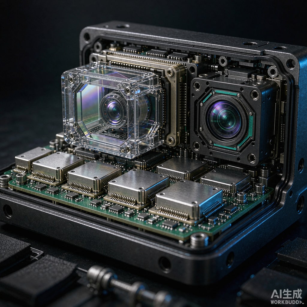
Modern driver assistance stacks pack SoCs, Gigabit SerDes links, and switching power supplies into millimeter-scale sensor modules, then place those modules next to ante
as for GNSS, cellular, and tire pressure monitoring. EMI shielding in automotive LiDAR and camera modules is therefore not a checkbox; it decides whether the vehicle passes CISPR 25 and whether the image pipeline survives without banding artifacts. This guide walks through the design decisions from noise inventory to validation.
Map the Noise Sources First
A camera module typically carries a CMOS image sensor, an ISP or bridge chip, a high-speed serializer such as GMSL or FPD-Link ru
ing 3 to 6 gigabits per second, and a buck converter for the 1.8 volt and 1.2 volt rails. Each is a distinct emitter: the serializer spreads broadband harmonics up to several gigahertz, the buck converter radiates at its switching frequency and harmonics, and the image sensor itself couples clock noise into its analog front end, which shows up as visible banding. A LiDAR module adds laser drivers with steep nanosecond-scale pulses, a rotating or MEMS sca
ing mechanism, and high-current rails that can exceed 10 amps transiently. List every source with its frequency range and coupling path before choosing any shielding hardware.
Shield Architecture for Fine-Pitch Sensor Boards
Board-level shields remain the workhorse. For dense mixed-signal layouts, a two-piece system, a soldered fence plus a removable or snap-on lid, lets production rework the sensor while keeping a closed conductive volume in the field. Where density is extreme, fine-pitch shield frames with integrated spring fingers accept lids at 1 millimeter or better pitches. Key mechanical rules: keep fence walls continuous with corner posts rather than relying on long unsupported spans; provide solder retention features sized for automotive vibration per the AEC-Q family expectations; and segment the cavity so that the laser driver in a LiDAR module does not share a can with the receiver photodiode front end, which is the most sensitive node on the board.
Multi-Sensor Arrays and Partition Walls
Modules that combine several cameras or a camera plus an imager benefit from partition walls inside a single shield footprint. A wall with a height below one twentieth of the shortest internal wavelength dimension, well-co
ected to the ground plane through the fence, isolates the transmit and receive sections cheaply. This is the same partition technique used in multi-cavity RF boards, and it prevents the classic failure mode where the illuminated laser couples directly into the avalanche photodiode bias line.
Absorbers and Ferrites Inside the Shield
A closed can reflects noise; sometimes you want it gone. Thin silicone loaded with carbonyl iron or ferrite powder, placed over the serializer or laser driver region, damps near-field resonances between the shield wall and the board, and suppresses cavity modes inside the can. Choose absorber thickness by frequency band: 0.2 to 0.5 millimeter sheets handle gigahertz-range SerDes noise, while thicker 1 millimeter material suits the lower hundreds of megahertz where buck converter harmonics live. Verify the material meets automotive temperature and flammability requirements before committing to it.
The Optical Window Problem
LiDAR windows and camera lens apertures are holes in the shield. Where the module must reject external fields, for example a LiDAR sharing a front bumper with a radar and a radio ante
a, a transparent conductive coating on the cover glass, typically indium tin oxide, restores shielding at the cost of a few percent of optical transmission. The coating must be edge-grounded continuously around its perimeter; an ungrounded ITO film behaves like a floating ante
a and can worsen coupling. Calculate whether you need it at all: for many camera modules behind a metal bracket, the bracket and gasket provide enough attenuation without touching the glass.
Grounding on Plastic Housings
Most automotive sensor modules live in plastic housings for styling and cost reasons, so the shield strategy must include how the internal can co
ects to the vehicle ground. Design a circumferential conductive gasket seat on the housing flange, bring the PCB ground to spring contacts or a dedicated ground plane region at the flange, and specify the gasket material, conductive fabric over foam or filled silicone, for the housing gap tolerance. Avoid pigtail grounds entirely; a short wide contact at several points around the flange keeps transfer impedance low at SerDes frequencies.
Validation: CISPR 25 and Beyond
Automotive validation runs emissions per CISPR 25 with the module powered in its realistic modes, including scan and transmit, and immunity per the ISO 11452 series. Add two sensor-specific checks. First, radiated immunity at frequencies that fall inside the image readout chain: a camera that shows rolling bands under a 100 volt per meter field at a cellular band will be flagged. Second, self-compatibility: verify GNSS and radio reception with every sensor active, because intra-vehicle interference is often caught only when all modules run together. Near-field scans during development localize which shield aperture or gasket gap leaks, long before the chamber slot.
Summary Checklist
Inventory every emitter and its band, segment cavities so laser drivers never share air with photodiode front ends, use fine-pitch two-piece cans with proper solder retention, apply thin absorbers where cavity resonance threatens the front end, ground optical coatings continuously or leave them out, and plan flange gasketing that carries SerDes-frequency currents. Modules designed this way pass CISPR 25 on the first or second chamber visit instead of the fifth.



