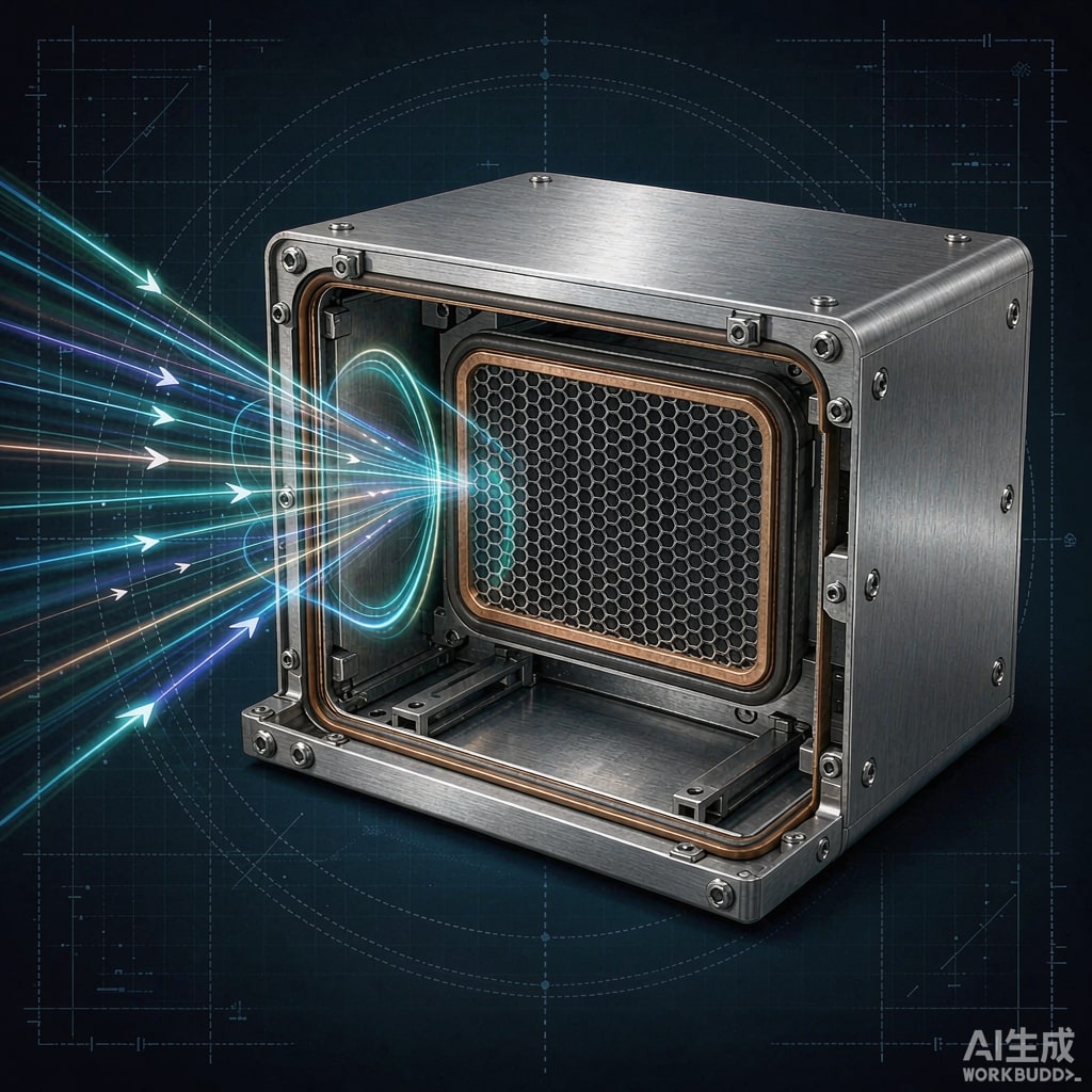
Why Perfect Shields Leak
A continuous metal enclosure would attenuate radiated emissions by well over 100 dB. Real enclosures are full of holes — ventilation openings, display windows, cable penetrations, LEDs, and the seams where two shield halves meet. At high frequencies these apertures behave as ante
as, and enclosure shielding effectiveness is set by the largest discontinuity, not by the metal itself. Aperture and seam design is therefore where most EMI battles are won or lost.
The Waveguide-Below-Cutoff Principle
A hole in a conductive wall acts as a short waveguide. Below its cutoff frequency, a waveguide attenuates energy exponentially rather than propagating it. For a single circular aperture of diameter d and material thickness t:
SE ≈ 27.3 × (t/d) dB (below cutoff)
For a rectangular slot of width w, the same relation uses w in place of d. Two consequences follow immediately:
- Depth helps: A deep, narrow opening — a dimpled hole, a louvered vent, a honeycomb — shields far better than a thin hole of the same diameter.
- Length hurts: Once the longest dimension of an opening approaches a fraction of a wavelength, it resonates and leaks efficiently. A 100 mm seam is a potent ante
a at 1.5 GHz (λ/2).
Aperture Design Rules
Single Apertures
Keep the maximum dimension of any single opening below λ/20 at the highest frequency of concern; λ/50 provides margin for production variation. For a 6 GHz threat, λ/20 is 2.5 mm — the reason display windows and speaker holes are covered with conductive mesh or transparent film instead of left open.
Arrays and Meshes
Multiple apertures close together leak as an array, with the array behaving like one larger aperture along its extent. Practical rules:
- Space holes at least several diameters apart when possible; adjacent-hole coupling erodes the single-hole attenuation.
- For ventilation, prefer many small holes or a honeycomb panel over slots. A honeycomb with 3 mm cells and 10 mm depth provides roughly 45 dB below its cutoff (about 60 GHz), while preserving airflow.
- Bond the mesh or honeycomb frame to the enclosure around its entire perimeter — a floating mesh contributes nothing.
Seams and Fastener Spacing
Two flanges held together by screws form a waveguide slot whose length is the distance between reliable contact points. Fastener spacing controls the leakage:
- Slot resonance: A seam of length L between good contacts resonates near L = λ/2. Halving the segment length raises the resonance an octave and cuts the leak dramatically.
- Spacing rule of thumb: Keep contact points closer than λ/20 at the highest frequency of concern; at 3 GHz that is 5 mm — impractical with screws alone, which is why conductive gaskets exist.
- Flange design: Wide, flat contact surfaces with a gasket compression limiter hold seam impedance low. A narrow raised land concentrates pressure and outperforms a wide, loosely compressed flange.
Where covers are removed for service, specify gaskets rather than relying on screw spacing — technicians will not re-torque to EMI tolerances.
Conductive Contact Strategies
A seam is only as good as the metal-to-metal contact across it:
- Conductive elastomer gaskets: Silver- or nickel-filled silicones fill gaps between flanges; choose filler chemistry compatible with the galvanic neighbors.
- Finger stock and spring contacts: Best for frequently opened doors; wipe action cleans contact surfaces.
- Surface finish management: Conductive conversion coatings (chromate on aluminum, tin or nickel plating on steel) maintain low seam impedance; anodize and paint are insulators and must be masked at gasket lands.
- Cable entries: Every cable crossing the shield needs 360° termination to the wall — a pigtail ground re-radiates the common-mode current it was meant to drain.
Verification on the Bench
Design rules set the starting point; measurement closes the loop. Near-field probes sweeping seams and apertures locate dominant leaks in minutes. For quantitative data, transfer impedance measurement of gasketed joints, or enclosure-level shielding effectiveness per IEEE 299, correlates design intent with production reality. Products bound for CISPR 32 or MIL-STD-461 should reserve test time for seam-level fixes — compressing a gasket or adding a screw is cheap before certification, expensive during it.
Conclusion
Enclosure shielding is governed by its worst opening. Treat every aperture as a waveguide, break long seams into short slots with fasteners and gaskets, guarantee conductive contact at every joint, and verify with near-field probing. Waveguide-below-cutoff arithmetic is simple; applying it consistently across the product is what separates a compliant enclosure from a leaky one.



