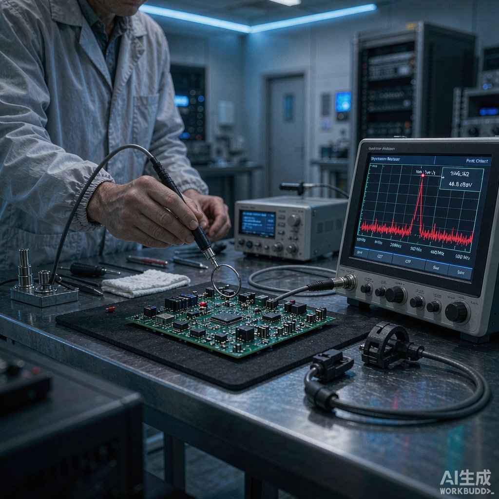
A full EMC compliance lab charges hundreds of dollars per day, and a failed submission costs weeks. Pre-compliance testing on your own bench catches the majority of emissions problems before the formal run, turning lab visits into confirmation rather than discovery. You do not need an anechoic chamber – a spectrum analyzer, a set of near-field probes, and a disciplined method will find most offenders. This guide walks through the toolkit, the measurements, and how to interpret results against CISPR 32 and FCC Part 15 limits.
The Bench Toolkit
Near-Field Probes
Near-field probes are small loops and stubs that sniff magnetic and electric fields centimeters from a board. They ca
ot measure absolute radiated emissions – the near field is not the far field – but they rank sources. A 1 cm H-field loop locates current loops: sweep it over the board with the unit ru
ing and the loudest spot is usually a switching loop, a cable common-mode choke point, or a ground stitch gap. E-field stubs highlight unterminated high-impedance nodes such as heatsink tabs and cable pigtails. Buy or wind a set from 1 cm to 5 cm; resolution comes from using the smallest probe that still shows signal.
Spectrum Analyzer Basics
A basic 9 kHz to 1 GHz tracking-generator analyzer is enough. Set RBW to 9 kHz or 120 kHz to mirror CISPR receiver bandwidths, use peak detection for fast scans and quasi-peak or average detection when comparing against limit lines. Max-hold traces while exercising the device – cycling loads, spi
ing fans, switching power states – so intermittent emissions appear. A 20 dB preamp helps resolve weak signals near the noise floor.
LISN and Line Isolation
Conducted emission testing requires a line impedance stabilization network between mains and the device under test. An off-the-shelf 50 uH LISN with a transient limiter feeds the analyzer a defined fraction of the line noise. Budget units are far cheaper than lab reference LISNs, and absolute calibration matters less than consistent relative measurement. Always run the DUT through an isolation transformer unless the LISN documentation explicitly supports direct mains, and ground everything to a common reference plane.
Conducted Emissions Quick Checks
With the LISN in place, scan 150 kHz to 30 MHz on both lines. The classic signatures are easy to read: broadband humps that track switching frequency point to the input filter of a converter, while narrow spikes at multiples of a clock point to digital noise coupling onto the line. Try a temporary clamp ferrite on the power cord – if a peak drops, the noise is common-mode and the fix is a better Y-capacitor layout or improved earthing, not a bigger X-cap. Compare results against the CISPR 32 Class B quasi-peak limits: 66 to 56 dBuV from 150 kHz to 500 kHz sloping down to 56 to 60 dBuV above 5 MHz.
Radiated Emissions Screening
True radiated testing needs distance and a calibrated ante
a, but screening works on a bench. Place the DUT a fixed distance – 1 or 3 meters – from a biconical or log-periodic ante
a in the quietest corner available, ideally outdoors or in a large room with metal walls far away. Scan 30 MHz to 1 GHz with max-hold while cycling modes. Cables dominate: a cable that resonates near a clock harmonic will scream in the data while the board looks quiet. Coil, shorten, or ferrite-load cables one at a time to attribute peaks to sources. Peaks that persist with cables dressed identically point to board-level loops – go back to near-field probes to localize them.
Interpreting Results Against the Limits
Treat bench numbers as relative and margin-driven. Because your setup is not calibrated to the lab’s, aim for 6 to 10 dB below limit lines on your own rig; a peak that just squeaks under on the bench usually fails in the chamber. Keep a log of trace screenshots with unit settings and cable dress, so fixes can be verified against the same conditions. When a design is within your margin, one lab pre-scan validates your correlation factor, after which your bench becomes a trustworthy gate for future revisions.
Common Fixes Found by Pre-Compliance
The same handful of fixes resolve most failures: slow the switching edge with a gate resistor or snubber; add or relocate Y-capacitors across the isolation barrier close to the transformer; stitch grounds across board splits so return currents stay under their signals; shield or twist cable pairs; and replace pigtails with 360-degree shield termination at co
ectors. Each fix takes minutes to try on the bench, which is precisely why pre-compliance pays for itself.
Conclusion
EMI pre-compliance does not replace the accredited lab, but it removes the surprise. Rank sources with near-field probes, screen conducted and radiated emissions against CISPR-derived limits with consistent margins, and iterate fixes on the spot. Designs that arrive at the lab with 6 dB of verified margin pass on the first visit.



