An EMI filter is a network designed against a specific source impedance and a specific load impedance. Change either one — as happens the moment the filter moves from a 50 ohm test fixture into a real product — and the attenuation curve you validated bears no relation to what the product does. This is the most common reason filtering passes on the bench and fails in the EMC chamber.
This guide covers component selection and placement for power and signal line filtering, with the impedance problem addressed rather than assumed away.
Why the 50 Ohm Insertion Loss Number Misleads
Filter datasheets specify insertion loss measured with 50 ohm source and 50 ohm load impedance. Real interfaces are rarely 50 ohms:
- A switching power supply input presents a low impedance at low frequency and a complex impedance through its resonant region.
- A cable looks like a transmission line with a characteristic impedance that depends on its geometry, terminated by whatever the far end presents.
- A signal driver is a low impedance source; a receiver may be high impedance.
A single-stage LC filter can be degraded substantially — in some impedance combinations, it can even amplify at certain frequencies — when the source and load impedances are mismatched in the wrong direction. The datasheet curve is a characterization, not a prediction.
Design Against Impedance, Not Against a Curve
The working rule for filter topology selection:
- If the source impedance is low and the load impedance is high, place the capacitor first (shunt element facing the low-impedance side), then the series element.
- If the source impedance is high and the load impedance is low, place the series element first, then the shunt.
In other words, the shunt element belongs on the side of the mismatch with the higher impedance, and the series element on the lower impedance side. This maximizes the filter’s effectiveness for the actual network rather than for a hypothetical 50 ohm one.
When both impedances are uncertain — which is common for a cable interface — a multi-stage filter or a feedthrough component with an integral ground plane is often more robust than trying to optimize a single stage for a guessed impedance.
Component Selection
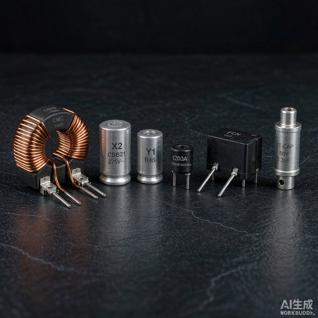
Capacitors
The capacitor is the workhorse of EMI filtering, and its real behavior is dominated by parasitics.
| Dielectric | Typical use | Key limitation |
|---|---|---|
| C0G / NP0 | Signal line filtering, RF bypass | Low capacitance density, larger case size for a given value |
| X7R | General bypass and filtering | Voltage and temperature coefficient, piezoelectric effects, DC bias derating |
| X5R | Bulk decoupling, cost-sensitive filtering | Wider tolerance, stronger DC bias derating than X7R |
| Film | Mains and high-voltage filtering, X and Y capacitors | Size, cost, limited high-frequency performance |
| Feedthrough / three-terminal | Interfaces where layout inductance is the limit | Cost, mounting requirements |
Three capacitor facts that decide whether a filter works:
- Self-resonant frequency sets the useful band. Above self-resonance a capacitor becomes inductive and stops attenuating. A 100 nF 0402 part may self-resonate around 20 to 30 MHz; beyond that it is helping less than you think.
- DC bias derating is real. An X7R capacitor at rated DC voltage may lose 50 to 80 percent of its nominal capacitance. Derive the effective value at the actual operating voltage, or the filter is detuned from your calculation.
- Parasitic ESL is the high-frequency limit. For a given case size, ESL is roughly fixed, and its impedance rises with frequency. Bypassing at high frequency requires several values in parallel, or a physically smaller part with lower ESL, placed as close to the interface as physically possible.
Inductors and Chokes
Inductor selection is usually the more engineering-heavy decision, because impedance depends on both inductance and the core material’s behavior.
- Differential mode — a standard inductor in each line, or a single inductor in the return path for signal lines. Choose high-permeability cores for low-frequency attenuation.
- Common mode — a coupled winding on a common core, which attenuates common mode currents while passing differential mode current without saturation. This is the standard approach for cable interfaces and DC power input lines.
- Saturation current must exceed the peak operating current, including transients and inrush. An inductor that saturates under load provides no attenuation and may generate distortion.
- Core material determines the frequency band. Manganese-zinc ferrites for lower frequencies, nickel-zinc for higher frequencies. Selecting a high-frequency material for a low-frequency problem wastes the component’s potential and vice versa.
- Self-resonance and inter-winding capacitance limit the upper frequency. For common mode chokes, poor winding separation effectively short-circuits the differential mode path and degrades performance.
Other Components
- Ferrite beads — behave as a frequency-dependent resistor above their transition frequency. Excellent for damping high-frequency noise on signal lines where a discrete inductor would be impractical. Select by the impedance at the frequency of interest, and remember that the impedance is resistive above transition, so it dissipates rather than reflects.
- TVS diodes — for transient and surge suppression, not continuous EMI attenuation. Placed at the interface to clamp incoming transients before they enter the filter.
- Gas discharge tubes — for high-energy surge protection on external interfaces, in coordination with a downstream TVS.
Placement and Layout
Layout decides the real attenuation, and no component choice can compensate for a bad one.
Shunt Elements Need a Real Ground
The capacitor’s attenuation depends on the impedance to ground, and that path includes the via, the trace, and the ground plane. A capacitor co
ected through a long thin trace to a distant ground point has an effective impedance dominated by the co
ection, not the component. Rules:
- Mount shunt capacitors so their ground terminal co
ects directly to the ground plane with vias adjacent to the pad. Two vias per terminal is a reasonable minimum.
- Keep the co
ection loop area small. The loop is the ante
a for the very noise you are trying to remove.
- Ground the shunt element locally, not at one distant star point. At the frequencies EMI filtering operates, a plane is far better than a star ground.
The Filter Is a Barrier
Place the filter at the physical interface, so that noise entering on the cable meets the filter before it reaches the rest of the board. The interface should be a barrier: filtered and unfiltered regions must not couple across it by other means.
- Keep unfiltered and filtered traces separated. Ru
ing them adjacent recreates the coupling path the filter was meant to block.
- No unfiltered signals across the barrier. Every line crossing the interface needs filtering, or the unfiltered line becomes the leak.
- Isolate the co
ector ground.
On heavily polluted interfaces, a partitioned ground with a defined coection point avoids injecting cable noise into the board reference plane.
Verification
Measure the assembled product, not the filter alone:
- Conducted emissions with a LISN, per the applicable standard and the correct measurement band.
- Insertion loss measured in the actual circuit with the actual source and load, if you want a number that predicts performance.
- Near-field probing to localize remaining emission sources before and after filter changes.
Iterate on placement first, component values second. In our experience roughly three quarters of filter shortfalls are layout and impedance problems, not component selection problems.
Summary
Design the filter for the impedances the network actually presents, not for 50 ohms. Choose capacitor dielectrics and values with an eye on self-resonance and DC bias derating rather than nominal capacitance. Choose inductor core materials for the frequency band of interest and verify saturation current. Then place everything so that the ground path is short and the interface is a genuine barrier. Do those four things and most conducted emission problems become solvable rather than mysterious.
Filter components are one part of a shielding and suppression strategy. If you are working through an interface design and want to match filtering against shielding gaskets and board-level measures, our engineers can help lay out the options.