## Why Copper Strip Mechanical Properties Matter for SMT Components
Copper strip is the foundational material for SMT co
ector contacts, lead frames, spring contacts, and EMI shielding components. Its mechanical properties—yield strength, ultimate tensile strength (UTS), and elongation—directly determine whether a stamped contact will maintain spring force over thousands of insertion cycles, whether a lead frame will resist deformation during die attach and wire bonding, and whether a progressive die can achieve the required forming geometry without fracture.
These properties are not abstract material science metrics. They are the engineering parameters that drive stamping die design, bend radius calculations, spring contact force modeling, and reliability predictions. When a co
ector contact loses insertion retention force after 500 cycles, the root cause traces back to copper strip yield strength and its work-hardening behavior during forming. Understanding and verifying these properties through proper tensile testing is essential for every SMT component manufacturer.
## Key Mechanical Properties and Their Manufacturing Impact
### Yield Strength (σ₀.₂): The Forming Threshold
Yield strength is the stress at which a copper strip begins permanent plastic deformation. For SMT applications, this property defines two critical boundaries:
1. Minimum forming force: Stamping press to
age and bend force calculations require yield strength data. Underestimating yield strength leads to underpowered press selection and incomplete forming; overestimating it wastes energy and increases die wear.
2. Maximum elastic recovery: After forming, copper strip springs back by an amount proportional to its yield strength relative to the forming stress. Higher yield strength alloys (like C19400 at 310-380 MPa) exhibit greater springback than pure copper C11000 (70-220 MPa), requiring more aggressive die geometry compensation.
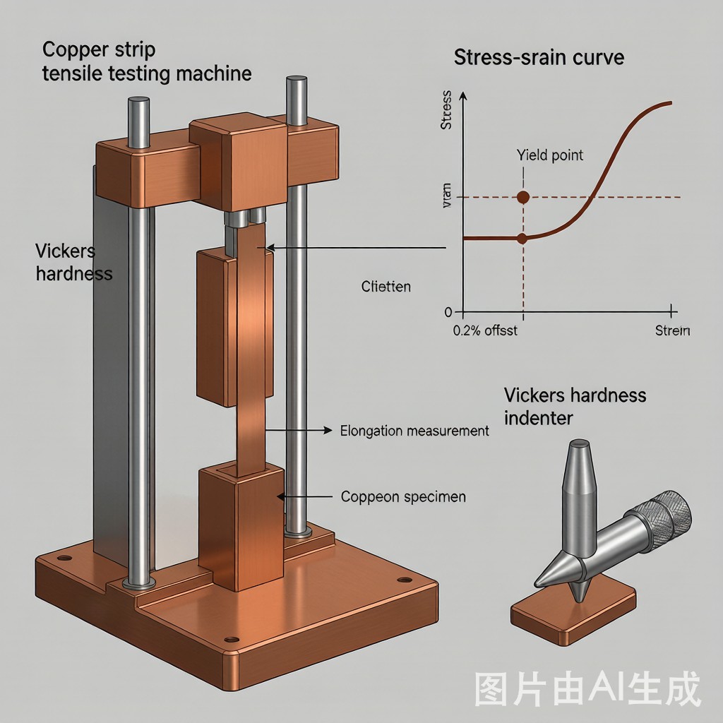
The 0.2% offset method (per ASTM E8/E8M) is the standard yield strength determination, measuring the stress at which the stress-strain curve deviates 0.2% from the elastic modulus line. This value is more repeatable than proportional limit measurements and is the universally accepted specification point.
### Ultimate Tensile Strength (UTS): The Fracture Boundary
UTS represents the maximum stress the copper strip can sustain before necking and fracture. In SMT manufacturing, UTS serves as:
– Fracture safety margin: Progressive die operations must keep forming stresses below UTS, typically with a 20-30% safety factor. A strip with UTS of 300 MPa should not be subjected to localized stresses exceeding 210-240 MPa in any die station.
– Work-hardening capacity: The difference between yield strength and UTS (the “strain hardening range”) determines how much additional strength the material gains during forming. Pure copper C11000 has a wide range (YS 70 MPa, UTS 220 MPa = 150 MPa hardening capacity), while tempered alloys have narrow ranges requiring precise forming control.
### Elongation (%): Formability Indicator
Elongation at fracture measures ductility—the material’s ability to undergo plastic deformation before breaking. For SMT co
ector stamping, elongation requirements vary by application:
| SMT Application | Minimum Elongation Required | Critical Forming Operations |
|—|—|—|
| Co
ector contact beams | 5-15% (tempered) | Beam bending, spring forming |
| Lead frame leads | 15-25% | Lead forming, coplanarity bending |
| Deep-drawn shielding cans | 25-40% (a
ealed) | Cup drawing, wall ironing |
| EMI spring contacts | 3-8% (hard tempered) | Sharp radius bending |
Insufficient elongation causes fracture at tight bend radii. Excessive elongation (over-soft material) produces spring contacts that lack retention force. The correct elongation value is application-specific, not a universal “higher is better” parameter.
## Copper Alloy Mechanical Properties Comparison
### Common SMT Copper Alloys and Their Property Ranges
| Alloy | Temper | YS (MPa) | UTS (MPa) | Elong. (%) | Primary SMT Application |
|—|—|—|—|—|—|
| C11000 (ETP Cu) | A
ealed | 70-90 | 210-230 | 30-45 | Bus bars, thermal straps |
| C11000 | 1/4 Hard | 140-170 | 240-270 | 15-25 | Lead frame forming |
| C11000 | 1/2 Hard | 220-250 | 270-300 | 8-15 | Co
ector contact beams |
| C19400 (Fe-Cu) | TH02 | 310-380 | 360-420 | 5-12 | IC lead frames |
| C19210 (Cu-Fe-P) | TH04 | 400-450 | 430-480 | 3-8 | High-strength lead frames |
| C26800 (65/35 Brass) | 1/2 Hard | 280-340 | 400-460 | 15-25 | Co
ector shells, terminals |
| C51000 (Phos. Bronze) | 1/2 Hard | 340-420 | 470-530 | 8-18 | High-reliability spring contacts |
| C7521 (Ni-Ag-Cu) | 1/4 Hard | 200-260 | 380-430 | 20-30 | EMI shielding spring clips |
These ranges reflect standard temper designations per ASTM B601. Actual lot-specific values vary within these ranges and must be verified through incoming tensile testing.
### Temper Selection Decision Framework
Choosing the correct temper for a SMT stamping application requires balancing three factors:
1. Forming severity: More severe forming (tighter bend radii, deeper draws) requires lower yield strength and higher elongation—use softer tempers
2. Functional strength: Higher spring force retention and insertion/extraction durability require higher yield strength—use harder tempers
3. Dimensional stability: Harder tempers exhibit less springback, producing more consistent formed geometry—but at the cost of reduced formability
The optimal temper sits at the intersection where formability is sufficient for the required geometry, and functional strength meets the application’s force retention requirements.
## Tensile Testing Standards and Procedures
### ASTM E8/E8M: The Standard Test Method
ASTM E8/E8M “Standard Test Methods for Tension Testing of Metallic Materials” is the authoritative procedure for copper strip tensile testing. Key requirements:
– Specimen geometry: Rectangular strip specimens per sub-size specimens (Figure 5 of E8), with reduced section width 6-12.5 mm and gauge length 25-50 mm
– Grip length: Minimum 50 mm beyond the reduced section to prevent grip-end fracture
– Strain measurement: Extensometer attached within gauge length for 0.2% offset yield determination; crosshead displacement is not acceptable for yield measurement
– Test speed: Stress rate ≤11.5 MPa/s during elastic region, or strain rate ≤0.015 mm/mm/s—excessive speed inflates yield strength readings by 5-10%
### Specimen Preparation from Production Strip
Tensile specimens must be cut from the same production strip being evaluated for stamping. Preparation guidelines:
– Cut specimens perpendicular to the rolling direction (transverse) if bend forming occurs across the strip width, or parallel (longitudinal) if forming follows the rolling direction
– Deburr specimen edges to prevent premature edge-initiated fracture
– Measure specimen width and thickness at three points within the gauge length (average for cross-section area calculation)
– Avoid shearing specimens—sheared edges introduce work-hardened zones that affect results; use milling or precision punching
### Testing Frequency and Sampling Plan
Incoming material verification and production monitoring require different testing frequencies:
– Incoming inspection: Minimum 2 specimens per lot (1 longitudinal, 1 transverse) for each alloy-temper combination
– Production monitoring: 1 specimen per 500 kg of strip processed, or 1 per production shift
– Failure investigation: 5 specimens minimum to establish statistical significance (calculate mean ±2σ range)
## Work Hardening and Its Impact on Formed Component Properties
### Strain Hardening Behavior During Stamping
Every bend, draw, or forming operation work-hardens the copper strip locally. The formed component’s final mechanical properties differ from the incoming strip’s properties because work hardening increases yield strength and reduces remaining ductility at the formed location.
For co
ector contact beams, this work hardening is actually beneficial—it increases the beam’s spring force beyond what the base temper would provide. However, for lead frame leads that undergo subsequent forming operations (coplanarity bend, clinch), excessive initial work hardening leaves insufficient remaining ductility for secondary forming.
### Predicting Work-Hardened Properties
The Hollomon equation (σ = K·εⁿ) approximates work hardening behavior, where K is the strength coefficient and n is the strain hardening exponent. Typical values:
| Alloy | K (MPa) | n | Work Hardening Rate |
|—|—|—|—|
| C11000 (a
ealed) | 315 | 0.30 | High—significant strengthening per bend |
| C19400 (TH02) | 480 | 0.12 | Moderate—limited additional hardening |
| C51000 (1/2H) | 600 | 0.08 | Low—near peak strength already |
| C26800 (1/2H) | 520 | 0.15 | Moderate |
These parameters allow finite element stamping simulations to predict formed component strength, enabling design engineers to select incoming strip temper based on the required final formed properties rather than the strip’s initial properties alone.
## Conclusion: Mechanical Data as a Manufacturing Foundation
Copper strip yield strength, tensile strength, and elongation are not merely certificate-of-compliance numbers to file away. They are the engineering parameters that determine whether your stamping die can form the required geometry, whether the formed contact will maintain spring force over its rated cycle life, and whether progressive die stations will operate within safe stress margins.
Investing in proper tensile testing per ASTM E8/E8M, tracking lot-to-lot variability, and correlating mechanical property data with stamping process parameters transforms material certification from a paperwork exercise into a manufacturing engineering discipline. For SMT co
ector and component manufacturers in Southeast Asia serving global OEMs, this mechanical data foundation supports the process validation documentation that customers increasingly require under IPC and JEDEC standards.



