A stamped SMT contact that loses 40 percent of its normal force in service is not a co
ector failure you will see in incoming inspection. It shows up eighteen months later as intermittent opens on a customer’s board. Stress relaxation is the mechanism behind that slow decay, and for copper strip it is the single most important property to qualify before a design freeze.
What Stress Relaxation Actually Measures
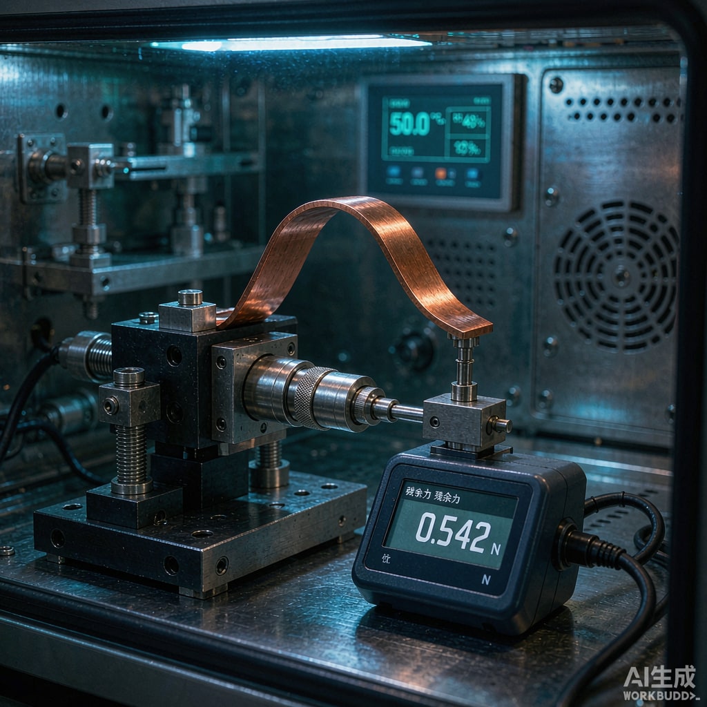
Stress relaxation is the loss of stress in a material held at constant strain. Bend a copper strip into a spring contact, clamp it in a housing, and the deflection never changes. The force the strip pushes back with does. At room temperature the loss is slow. Above roughly 80 C it accelerates sharply, because the mechanism is thermally activated.
Two mechanisms operate:
- Dislocation glide and rearrangement dominates below about 150 C. It is recoverable in principle but not in practice once the contact geometry has been locked by the housing.
- Grain boundary diffusion and recovery takes over at higher temperatures and becomes the governing mechanism for long-term field life.
The practical consequence: a test at 150 C for 1000 hours does not simply equal 1000 hours at 150 C in the field. It is a proxy that must be converted through an Arrhenius or Larson-Miller relationship. Getting that conversion right is where most specifications go wrong.
The Standard Test Setup
Fixture and Deflection
The test fixture deflects a strip specimen to a fixed strain and holds it. Two configurations dominate:
- Cantilever beam — one end clamped, load applied at a known overhang. This matches most stamped SMT contacts and gives a clean bending stress calculation.
- Three-point bend — better for wide strip and for materials where you need to avoid the stress concentration at a clamp.
Initial stress should be set in the range the contact will actually see. A contact designed for 100 grams of normal force at 0.25 mm deflection should be tested at that deflection, not at a convenient round number. Testing at double the design deflection produces data that looks reassuringly stable and predicts nothing useful.
Temperature and Duration
Standard practice per ASTM E328 and the equivalent JIS and IEC methods uses a matrix:
| Temperature | Typical duration | What it correlates to |
|---|---|---|
| 85 C | 1000 h | General industrial, mild thermal load |
| 105 C | 1000-3000 h | Consumer electronics, near-power components |
| 125 C | 1000 h | Automotive under-hood class, accelerated |
| 150 C | 1000 h | Severe acceleration, screening only |
Run at least three temperatures if you intend to extract an activation energy. A single temperature gives you one data point and no basis for extrapolation.
Measurement
Measure residual force in situ with a load cell, or extract and measure periodically. In-situ is strongly preferred because extraction itself perturbs the stress state. Log the first hour densely — a large fraction of total loss in some alloys happens in the first 10 hours and is invisible if your first measurement is at hour 100.
Reading the Data
Plot residual stress ratio against log time. Most copper alloys produce a curve with three recognizable phases:
- Primary transient — rapid initial loss, roughly the first 10 to 100 hours. Driven by dislocation rearrangement.
- Steady-state logarithmic decay — a nearly straight line on a log-time plot. This is the phase that determines field life, and where you should fit your model.
- Accelerated terminal loss — appears when the alloy begins to overage or when recrystallization starts. If your data turns down sharply, you have exceeded the useful temperature for that alloy.
Extrapolation and the Arrhenius Trap
A Larson-Miller or Arrhenius extrapolation from 150 C data back to a 60 C field condition can easily span four orders of magnitude in time. Small errors in activation energy produce enormous errors in predicted life. Two guards:
- Extract activation energy from a multi-temperature test, not from literature values. Alloying additions and temper change it substantially.
- Cap extrapolation at two orders of magnitude beyond your longest test. If you need more, run a longer test.
Comparing Copper Strip Alloys
Stress relaxation resistance tracks the same hierarchy as softening resistance, and for the same reason: it is governed by how well the microstructure resists dislocation motion at temperature.
C11000 (ETP Copper)
Excellent conductivity at 100 percent IACS, poor relaxation resistance. Above 100 C, C11000 in a spring application will lose force quickly. It is a conductor, not a spring. Use it where the contact is over-designed or where the thermal load is low.
C26000 Brass
Moderate strength, moderate cost, and relaxation behavior that depends heavily on temper. Spring temper brass is acceptable to about 100 C. It is widely used in low-cost SMT contacts where the housing provides some mechanical preload that compensates for force loss.
C51000 Phosphor Bronze
Tin-phosphor bronze is the historic workhorse for co
ector springs. Relaxation resistance is meaningfully better than brass, good to roughly 125 C, and the alloy is easy to stamp and plate. For most SMT contact applications it is the correct default.
C7025 (CuNiSi)
Copper-nickel-silicon alloys are precipitation hardened and retain force far better than phosphor bronze at 125 to 150 C. The trade-off is lower conductivity and a temper that must be developed correctly during mill processing. Where a co
ector must survive 150 C and hold force, C7025 or a similar CuNiSi grade is the standard answer.
C17200 (Beryllium Copper)
The best relaxation resistance of the common copper strip alloys, usable to 200 C in some tempers, with strength that phosphor bronze ca
ot reach. The cost and the regulatory burden of beryllium handling keep it reserved for high-reliability and high-temperature applications.
Design Rules That Reduce the Risk
- Design for force loss, not for initial force. Size the spring so that the force after the projected relaxation is still above the minimum contact force your interface needs. For gold-on-gold dry circuits this may be as low as 20 to 30 grams. For tin-plated interfaces, where the contact must fracture and penetrate an oxide layer, you need considerably more.
- Lower the operating temperature. A 20 C reduction in the contact’s steady-state temperature can halve the relaxation rate. This is often cheaper than upgrading the alloy — look at copper pours, thermal relief, and co
ector placement before you switch materials.
- Reduce the strain. Design the contact to reach its working force at a lower fraction of the elastic limit. A contact operating at 60 percent of yield relaxes more slowly than one at 85 percent, in the same alloy.
- Avoid stress concentrations. A sharp inside radius on the bend concentrates stress and becomes the initiation point for relaxation and eventually cracking. Specify an inside bend radius of at least 0.5 times the strip thickness, and prefer 1.0 times for high-temperature parts.
- Control grain direction. Bend lines should run perpendicular to the rolling direction wherever the layout allows. Bending parallel to the grain gives lower and less consistent springback.
What to Put in a Purchase Specification
A copper strip specification that will actually protect you against relaxation failures should state:
- Alloy designation and temper, in a standard system such as UNS plus temper code
- Tensile strength and yield strength ranges, with the test direction specified
- Residual stress ratio after a defined exposure, for example 70 percent minimum after 1000 hours at 125 C at 0.2 percent offset strain
- Grain size range, since coarse grains relax faster than fine ones in the same alloy
- Strip thickness tolerance and camber limits, because both affect the as-formed stress state
- Surface condition and any passivation or anti-tarnish treatment, which affects solderability but not relaxation
Ask your supplier for the relaxation data behind the claim, not just the claim. A residual stress ratio without a stated temperature, time, and initial stress level is not a specification, it is a marketing line.
The Bottom Line
Stress relaxation is a slow, thermally driven loss of contact force that no incoming inspection will catch. Qualify it deliberately: test the actual alloy and temper at the actual design deflection, run a multi-temperature matrix if you need to extrapolate, and design the spring so it still works when the force has decayed by the amount your data predicts. Copper strip alloy choice is the largest single lever, but contact temperature and strain level are close behind, and both are usually cheaper to change.
If you are specifying copper strip for a high-temperature SMT contact and need relaxation resistance data alongside the mechanical and plating properties, our engineering team can walk through the alloy options and the test evidence behind them.