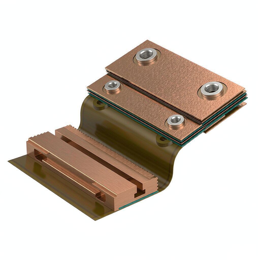
Rigid-flex PCBs combine flexible polyimide circuits with rigid sections for co
ectors, components, and mechanical mounting. One of the quiet workhorses in this construction is copper strip: it serves as stiffener material, as bonded shielding layers over flex regions, and as the raw foil from which manufacturer-supplied stiffener laminates are made. Choosing the wrong alloy or thickness shows up later as delamination, cracked solder joints at the flex-to-rigid transition, or shielding that fails in the EMI chamber. This guide covers the practical selection parameters.
Why Copper Strip in Rigid-Flex Construction
Stiffeners do three jobs: they add local rigidity where components are soldered so the flex does not move during reflow, they set the final assembly thickness so ZIF co
ector contacts grip correctly, and they dissipate heat from hot components through the polyimide. In many designs the same copper layer also acts as an EMI shield, because a bonded copper plane over the flex region shortens return paths and blocks radiated noise from high-speed traces.
Stiffener Requirements
A stiffener is not electrically functional in most cases, so the alloy can be simple. C11000 (electrolytic tough pitch) copper strip is the default: 100% IACS conductivity, excellent adhesion to acrylic and adhesiveless polyimide bondplies, and low cost. Thickness is the main variable. Common stiffener thicknesses run from 0.1 mm to 0.4 mm; for component-bearing areas, 0.2–0.3 mm keeps the flex flat enough for a reliable reflow profile. For ZIF co
ector ends, the total finished thickness tolerance (stiffener plus adhesive plus coverlay) is typically ±0.05 mm — confirm this with your flex fabricator before ordering, because the ZIF spec, not the copper spec, drives the stack-up.
Shielding Layer Requirements
When the copper doubles as a shield, conductivity across the whole area matters, and C11000 still works. But shielding planes need vias or edge contacts stitched to ground, so surface preparation and oxidation control become important. A thin a
eal-friendly oxide treatment, or an OSP-type strippable coating before lamination, protects solderability of the stitch points. For designs where the shield must attenuate magnetic fields or carry significant return current, a heavier 35–70 µm (1–2 oz) copper is preferred over 17 µm (0.5 oz) foil.
Alloy Selection: C11000 vs C19400 vs Brass
C11000 is the default, but two alternatives earn their place:
- C19400 (Cu-Fe-P): If the stiffener also carries current — for example a bonded power bus over the flex — C19400 offers roughly 65% IACS with double the strength and better creep resistance at temperature. It is easier to stamp fine slots in C19400 than in C11000 for selective stiffener shapes.
- Brass (C26000): Occasionally used for mechanical-only stiffeners where the supplier wants maximum dimensional stability and low cost. Brass conductivity is only ~28% IACS, so never use it where heat spreading or shielding is intended.
For dynamic flex regions (bending in service), avoid bonding thick copper anywhere on the flex section. Stiffeners belong on the rigid islands or at co
ector ends only; a stiff copper patch in a dynamic bend is the classic cause of trace cracking within a few thousand flex cycles.
Thickness Selection Rules
Component Areas
Use 0.2–0.3 mm C11000 under BGA, QFN, or co
ector footprints. The goal is to raise the local bending stiffness (proportional to thickness cubed) enough that the flex does not flex during reflow. Doubling thickness from 0.15 mm to 0.3 mm increases stiffness roughly 8×, which is why thin stiffeners disappoint.
ZIF Ends
Drive the stack-up from the co
ector datasheet. Typical ZIF insertion ranges accept 0.20–0.35 mm total; the copper stiffener at 0.1–0.15 mm with a thin bondply is common.
Shield Planes
17–35 µm bonded foil suffices for electric-field shielding above 30 MHz in most IoT and consumer designs. Go to 70 µm when the shield plane also carries multi-ampere return currents, as in power-over-flex designs.
Bonding and Adhesion Quality
The failure mode that matters is adhesion loss, not copper strength. Peel strength between copper and polyimide should meet IPC-TM-650 method 2.4.9, with values above 1.1 N/mm (6 lb/in) after solder floating for standard constructions. Specify:
- Treated (toothed) copper surface for adhesiveless bondplies; bright a
ealed surface performs poorly on direct bonding.
- Copper surface roughness Rz 3–6 µm as a middle ground — enough tooth for adhesion, not so rough that thin flex traces etch unevenly.
- Stress-relief a
ealed temper (soft) for stiffener stock that will be bonded flat; half-hard stock warps after bonding due to residual stress.
Handling, Cleaning, and QA
Copper stiffener stock oxidizes during storage. Keep coils sealed with VCI paper and use within 6 months. Before lamination, clean with a mild acidic micro-etch to remove oxide; do not skip this even if the copper “looks fine” — invisible oxide halves peel strength. Incoming QA on strip should check thickness across the coil width, camber, and a peel-strength coupon. For shield applications, add a surface resistance check (below 5 mΩ across a 100 mm span) to catch contamination or heavy oxide before it becomes a field failure.
Practical Specification Checklist
- Alloy: C11000 default; C19400 when current-carrying or fine-slash stamping needed.
- Thickness: 0.2–0.3 mm component stiffeners; 17–70 µm shield planes per current needs.
- Temper: stress-relief a
ealed for bonding; avoid half-hard for flat lamination.
- Surface: treated/toothed for bondply adhesion; oxide-free at delivery.
- Tolerances: thickness ±5% or better; camber below 1 mm/m.
- Peel strength: ≥1.1 N/mm per IPC-TM-650 2.4.9 after solder float.
Specified this way, copper strip stiffeners and shielding layers last the full product life without delamination surprises. Most field failures in rigid-flex assemblies trace back to two avoidable mistakes: stiff copper in a dynamic bend area, and bonding over oxidized stock. Eliminate those two and the rest is routine fabrication.



