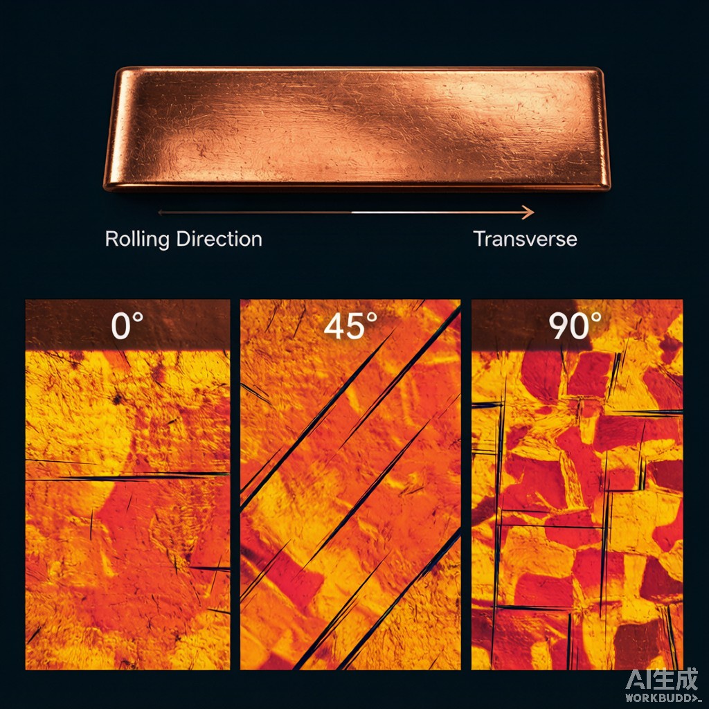
Introduction: The Hidden Cost of Anisotropy in SMT Terminal Forming
In high-volume SMT co
ector manufacturing, a progressive die stamps thousands of terminals per minute. Each terminal undergoes multiple bending operations — 90° bends, U-bends, Z-bends — executed at different orientations relative to the rolling direction of the copper strip. When the same die tooling produces terminals with inconsistent bend angles, dimensional variation, or springback variation across production runs, the root cause is often overlooked: plastic anisotropy — the directional dependence of mechanical properties in rolled copper strip.
This article examines the metallurgical origins of copper strip anisotropy, its practical measurement through the Lankford coefficient (r-value), its consequences for multi-bend SMT terminal forming, and engineering strategies to control earing and dimensional variation in high-speed stamping operations.
The Metallurgical Origin of Plastic Anisotropy
Crystallographic Texture Development During Rolling
When copper strip is cold-rolled to final gauge thickness (typically 0.1–0.5 mm for SMT applications), the plastic deformation reorients the crystal lattice of individual grains. Over multiple rolling passes, a preferred crystallographic orientation — known as rolling texture — develops. This texture is not random; specific crystallographic planes and directions align with the rolling geometry, creating directionally dependent mechanical properties.
In FCC metals like copper and brass, three primary texture components dominate after cold rolling:
| Texture Component | Miller Indices | Characteristics | Typical Alloys |
|---|---|---|---|
| Copper texture | {112}<111> | High stacking fault energy metals, strong at high reductions | C11000 (ETP), C19400 (CuFe2P) |
| Brass texture | {110}<112> | Low stacking fault energy metals, shear band formation | C26000 (70/30 Brass) |
| Cube texture | {100}<001> | Recrystallization texture after a
ealing, high formability |
A
ealed C11000, C19400 |
The key insight for SMT terminal manufacturing: the brass texture ({110}<112>) produces strong planar anisotropy with r-values significantly above 1.0, while the copper texture ({112}<111>) produces more isotropic behavior. A
ealed tempers with recrystallized cube texture ({100}<001>) are the most isotropic — and therefore the most predictable — for multi-bend forming operations that involve bends in multiple directions.
Crystallographic Effect on Bending Mechanics
When a copper strip is bent, the outer surface experiences tensile strain while the i
er surface undergoes compressive strain. The crystallographic orientation determines which slip systems (specific {111}<110> combinations in FCC metals) activate to accommodate this strain. If the active slip systems differ between the rolling direction (0°) and the transverse direction (90°), the bending behavior — including bend radius limits, springback angle, and resistance to cracking — will differ by orientation.
A terminal that bends reliably when the bend line is parallel to the rolling direction may crack or over-springback when the bend line is perpendicular. In progressive dies where material orientation is fixed by the coil feed direction, orientation-sensitive bend features must be designed with the known anisotropy characteristics of the selected alloy and temper.
Measuring Anisotropy: The Lankford Coefficient (r-value)
ASTM E517 Test Methodology
The plastic strain ratio (r-value), also called the Lankford coefficient, is the primary quantitative measure of plastic anisotropy in sheet metals. It is defined as the ratio of true width strain (ε_w) to true thickness strain (ε_t) during a uniaxial tensile test:
r = ε_w / ε_t = ln(w/w₀) / ln(t/t₀)
An r-value of 1.0 indicates isotropic behavior. Values above 1.0 indicate resistance to thi
ing (the material narrows more than it thins) — favorable for deep drawing. Values below 1.0 indicate easy thi
ing — unfavorable for forming operations requiring material flow.
For SMT terminal bending, the relevant metric is planar anisotropy — the variation of r-value with orientation in the sheet plane. This is quantified by the normal anisotropy (r̄) and planar anisotropy (Δr):
r̄ = (r₀ + 2·r₄₅ + r₉₀) / 4
Δr = (r₀ – 2·r₄₅ + r₉₀) / 2
Where r₀, r₄₅, and r₉₀ are r-values measured at 0°, 45°, and 90° to the rolling direction.
R-Values for Common SMT Copper Strip Alloys
| Alloy | Temper | r₀ (0°) | r₄₅ (45°) | r₉₀ (90°) | r̄ | Δr | Planar Anisotropy Rating |
|---|---|---|---|---|---|---|---|
| C11000 (ETP Cu) | H02 (½ hard, cold-rolled) | 0.85 | 1.10 | 0.95 | 1.00 | -0.20 | Low |
| C11000 (ETP Cu) | O60 (a
ealed, recrystallized) |
0.95 | 1.00 | 1.05 | 1.00 | 0.00 | Negligible (isotropic) |
| C19400 (CuFe2P) | H02 | 0.80 | 0.95 | 1.10 | 0.95 | 0.00 | Low |
| C26000 (Brass) | H02 | 1.10 | 1.60 | 1.30 | 1.40 | -0.40 | High |
| C26000 (Brass) | O60 (a
ealed) |
0.90 | 1.30 | 1.00 | 1.13 | -0.35 | Medium-High |
| C52100 (Phosphor Bronze) | H02 | 0.75 | 0.85 | 0.90 | 0.84 | -0.03 | Low |
Brass C26000 in the H02 temper exhibits the strongest planar anisotropy (Δr = -0.40), with r-values varying by over 50% between orientations. This means a C26000 terminal strip will show markedly different bend behavior — springback angle, cracking tendency, and dimensional recovery — depending on whether the bend line is parallel to or diagonal to the rolling direction.
In contrast, a
ealed C11000 ETP copper is nearly isotropic (Δr ≈ 0), making it the preferred choice for complex multi-bend terminals where orientation consistency is critical.
Earing: The Visible Consequence of Anisotropy
Earing Formation Mechanism
During cup drawing operations — common in SMT co
ector shell and contact housing forming — planar anisotropy causes the cup rim to be non-uniform in height. The rim develops peaks (ears) at orientations where the r-value is highest and valleys where it is lowest. This phenomenon, called earing, is the most visible and costly consequence of plastic anisotropy in SMT manufacturing.
For a negative Δr (as in C26000 brass), ears form at 45° to the rolling direction — producing a characteristic 4-ear pattern at 45°, 135°, 225°, and 315°. For a positive Δr (less common in copper alloys), ears form at 0° and 90° — a 2-ear pattern. The earing percentage quantifies the severity:
Earing (%) = (h_ear – h_valley) / h_valley × 100
| Alloy (O60 Temper) | Typical Earing (%) | Ear Pattern | Trim Loss Impact |
|---|---|---|---|
| C11000 (a
ealed) |
2–4% | Weak 4-ear or none | Minimal |
| C19400 | 3–6% | Weak 4-ear | Low |
| C26000 (a
ealed) |
8–15% | Strong 4-ear (45°) | Moderate to high |
| C26000 (½ hard) | 12–20% | Strong 4-ear (45°) | High |
| C52100 | 3–7% | Weak 4-ear | Low |
For drawn co
ector shells, earing above 8% requires an additional trimming operation — adding one die station and increasing material waste by 5–12%. For high-volume production (millions of parts/year), this translates to significant cost. The most effective engineering control for earing is temper selection: a
ealed tempers with recrystallized cube texture consistently produce lower earing than cold-worked tempers.
Practical Impact on Multi-Bend SMT Terminals
Bend Orientation Within the Progressive Die
In a progressive die, the copper strip feeds in a fixed direction (the rolling direction). Bends are designed with specific orientations relative to this feed direction. A terminal with three bends at 0°, 45°, and 90° to the rolling direction will exhibit three different bend behaviors due to the varying r-values at each orientation.
Specifically:
- 0° bends (bend line parallel to rolling): Typically easier forming, lowest springback, but may be subject to cracking if the alloy has low ductility in the rolling direction due to work hardening.
- 45° bends: For brass alloys, this orientation has the highest r-value — meaning the material resists thi
ing and may require higher forming forces. The bend radius may need to be increased by 20–30% compared to 0° bends to avoid outer-fiber cracking.
- 90° bends (bend line perpendicular to rolling): Intermediate behavior for most copper alloys. Springback is typically 10–20% higher than 0° bends due to the different distribution of residual stresses from the rolling process.
Springback Variation Across Orientations
Springback — the elastic recovery after bending that causes the final bend angle to be less than the tool angle — is directly influenced by crystallographic texture. For C26000 brass in the H02 temper:
| Bend Orientation | Target Angle | Required Die Angle (compensation) | Springback Amount |
|---|---|---|---|
| 0° (parallel) | 90.0° | 87.5° | 2.5° |
| 45° | 90.0° | 86.0° | 4.0° |
| 90° (transverse) | 90.0° | 87.0° | 3.0° |
The 60% higher springback at 45° compared to 0° is a direct consequence of the higher r-value at 45° — the material’s greater resistance to thi
ing translates to a larger elastic recovery component. Die designers must either (a) use different bend angles per station for different orientations, or (b) design the terminal layout so that all critical bends are at the same orientation.
Engineering Strategies for Anisotropy Control
Material Selection Decision Matrix
| Terminal Complexity | Bend Orientations | Recommended Alloy + Temper | Rationale |
|---|---|---|---|
| Simple (1–2 bends, same direction) | Single orientation | C52100 H02 or C26000 H02 | Anisotropy has minimal impact; choose for spring properties or cost |
| Moderate (3–4 bends, mixed orientation) | 0° + 90° | C19400 O60 or C11000 O60 | Low anisotropy, predictable springback |
| Complex (5+ bends, all orientations) | 0° + 45° + 90° | C11000 O60 (a
ealed) |
Near-isotropic; r̄ ≈ 1.0, Δr ≈ 0 |
| High spring force required | Any | C52100 H02 | Accept anisotropy; design bends at single orientation |
Process Optimization
Beyond material selection, several process strategies mitigate anisotropy effects:
- Stress-relief a
ealing:
A low-temperature aeal (250–350°C for C11000, 300–400°C for C26000, 15–30 minutes) after the first bending station reduces residual stresses and partially randomizes the deformation texture, reducing springback variation by 20–40% for subsequent bends.
- Rotary bending: Replacing fixed V-die bending with rotary bending tools reduces the effect of sheet anisotropy on bend angle by 30–50%, as the rotating bending leaf accommodates variable material flow.
- Terminal layout optimization: Rotating the terminal design on the strip layout so that all tolerance-critical bends are at the same orientation (ideally 0° or 90°) eliminates the need for orientation-specific die compensation.
- In-die angle monitoring: Laser or camera-based angle measurement after the final bend station enables closed-loop die adjustment, compensating for anisotropy-driven variation across coil batches.
Southeast Asian Manufacturing Considerations
In tropical stamping environments (30–35°C, 80–95% RH), two additional factors interact with anisotropy:
Temperature-induced recovery: At 35°C ambient, the copper strip in the progressive die accumulates thermal energy that promotes partial dislocation recovery between stations. This thermal recovery is orientation-dependent — it reduces the stored energy in grains with high Taylor factors (hard orientations) more than in soft orientations, effectively reducing the Δr value by 10–15% compared to 20°C laboratory conditions. This means terminals that pass QC in an air-conditioned metrology lab may exhibit different dimensions when stamped in an unconditioned factory.
Lubricant viscosity and friction anisotropy: The surface texture of rolled copper strip is itself anisotropic — with a directional roughness pattern (Ra typically 0.8–1.2 μm along rolling vs 1.0–1.6 μm transverse). In tropical heat, stamping lubricant viscosity decreases by 30–50%, amplifying friction anisotropy and potentially increasing bending force variation between orientations.
Conclusion
Plastic anisotropy in rolled copper strip is not a material defect — it is an inherent consequence of the thermomechanical processing that gives SMT terminal materials their strength, conductivity, and formability. The engineering challenge is to understand, measure, and control its effects on multi-bend terminal forming. By selecting alloys and tempers with appropriate anisotropy characteristics, orienting critical bends consistently within the strip layout, and implementing in-process monitoring and compensation, manufacturers can achieve tight dimensional tolerances despite the directional nature of rolled copper strip. For the most demanding applications, a
ealed C11000 ETP copper with its near-isotropic cube texture remains the benchmark for predictable, orientation-independent forming behavior.



