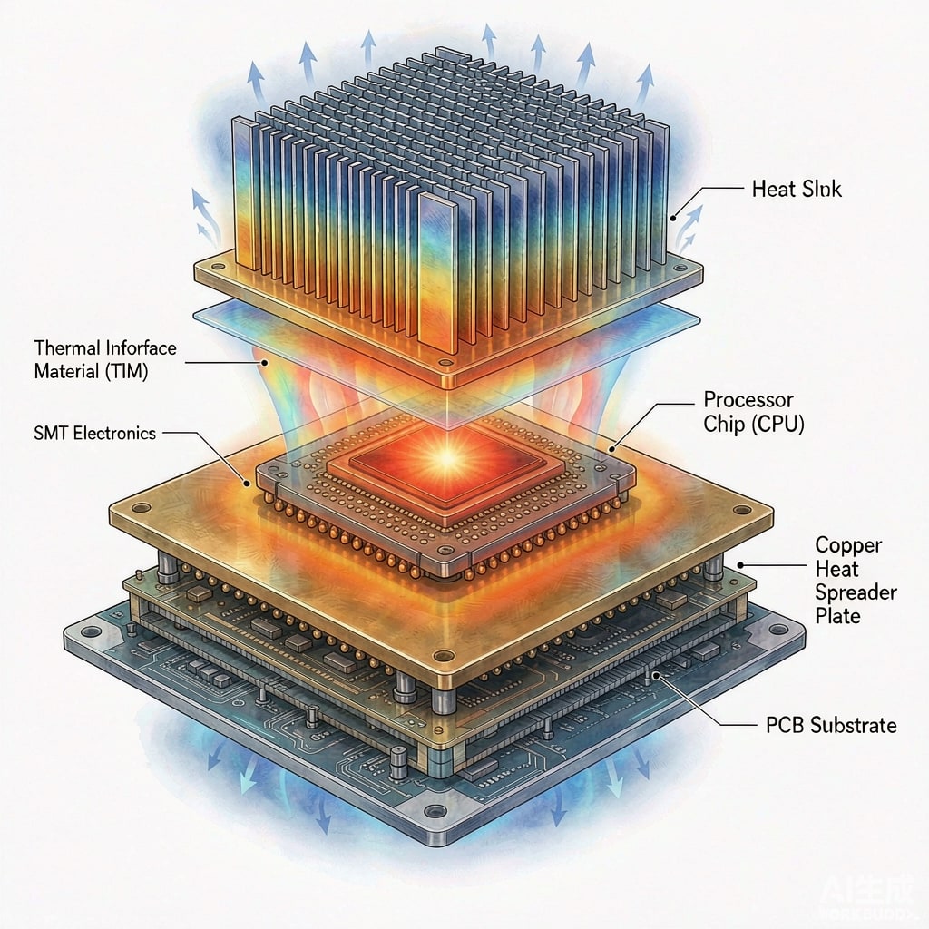
Why Hot Spots, Not Average Temperature, Limit SMT Designs
Most PCB thermal failures trace back to a single component that runs far hotter than the board average. A DC-DC converter, an RF power amplifier, or a processor can dissipate 5-15 W into a few square centimeters while the surrounding copper planes stay comparatively cool. The limiting factor is not how much heat the system can eventually reject, but how effectively heat is spread from that concentrated source before it reaches a heat sink or an enclosure wall. This spreading bottleneck is quantified as spreading resistance, and it is the reason a generously sized heat sink on a small die still delivers disappointing results.
Copper strip heat spreaders address the problem at the right location: directly between the source and the cooling path. Because oxygen-free and electrolytic copper conducts roughly 390-400 W/m·K, a thin copper plate inserted under the hot component pulls the heat footprint outward, lowering the peak junction temperature even when total power is unchanged.
The Physics of Spreading Resistance
When heat enters a heat sink base from a small die area, the flux must turn and fan out laterally. Near the source, the effective cross-section is small, so the local thermal gradient is steep. Spreading resistance depends on three ratios: source size to spreader size, source size to spreader thickness, and source size to fin-field area.
Rules of Thumb
- Optimal spreader thickness typically falls between 1.0 and 3.0 mm for sources of 10-25 mm per side. Thi
er plates under-spread; thicker plates add conduction resistance without benefit.
- The spreader should extend laterally at least 2-3 times the source half-width to reach most of the available benefit.
- For very small sources (under 5 mm), a vapor chamber or embedded heat pipe may outperform solid copper because lateral spreading distance becomes too long for conduction alone.
A practical estimate: adding a well-sized copper spreader between a 15×15 mm source and its heat sink commonly reduces total thermal resistance by 15-30%, which translates directly to junction temperature margin.
Where Copper Strip Fits in the Stack
There are two common architectures. In the first, the spreader is a stamped or machined copper plate mounted on the PCB underside or on top of the board under the heat sink, with thermal interface material on both sides. In the second, used in high-volume products, thin copper strip (0.3-1.5 mm) is formed into an integrated carrier that also serves mechanical functions: standoff, EMI containment lip, or screw boss.
Alloy and Temper Selection
- C11000 (ETP copper) at 391 W/m·K is the default for pure thermal duty where forming is minimal.
- C10200 (OFHC) suits vacuum-brazed or hydrogen-fired assemblies where internal oxidation of ETP copper would matter.
- Where the spreader doubles as a spring clip or EMI finger, C19400 or C7025 trades about 15-25% of conductivity for much higher yield strength and stress-relaxation resistance.
Half-hard temper is usually the best compromise: enough formability for a gentle coin or bend, enough stiffness to survive handling without oil-ca
ing.
Attachment Methods and Their Thermal Cost
The spreader helps only if its interfaces are good. Each interface adds contact resistance, and thin layers are essential.
Common Options
- Thermal adhesive or epoxy bond line (50-150 µm): simple and mechanically robust; expect 0.3-0.8 °C·cm²/W per interface depending on filler loading.
- Solder attachment: best performance (bond line 25-75 µm) but demands CTE management; direct copper-to-FR-4 solder joints crack over cycling, so a stress-relief layer or compliant frame is used.
- Compression with screws plus thermal grease or pad: serviceable and reworkable; requires even screw torque in a star pattern to avoid bowing the spreader and opening gaps at the corners.
Two interfaces (source-to-spreader, spreader-to-sink) mean the choice of TIM matters as much as the copper. A cheap pad with 3 W/m·K can erase the spreader’s advantage; a 6-8 W/m·K grease or phase-change film preserves it.
Electrical and EMI Considerations
A copper spreader is also a large floating conductor. Decide deliberately whether to bond it to ground. Bonding gives EMI benefits: the plate acts as a shield plane and can suppress radiated emissions from underneath the RF section. But bonding to a different ground potential than the PCB planes can invite ground loops, and uncontrolled contact through mounting hardware creates intermittent co
ections that behave like ante
as. Use deliberate, multi-point grounding with predictable impedance, or isolate with anodized coatings and insulating washers – never leave it ambiguous.
Verification: Measure the Spreading Benefit
Validate the design with three measurements:
- IR thermography of the populated board, comparing peak source temperature with and without the spreader under identical power and airflow. Look at the footprint contour, not just the peak.
- Thermocouple on the spreader surface 10-15 mm from the source edge to confirm the heat is actually traveling laterally; a flat gradient over that distance means the spreader is thick enough.
- Torque and re-assembly repeatability: repeat the test after one removal/reinstallation cycle to confirm the TIM and screw scheme reproduce the same result.
Procurement Notes for Spreaders Made From Strip
When sourcing formed copper strip spreaders, specify material to ASTM B152 (C11000/C10200), state temper (typically half hard), require flatness better than 0.5 mm over the part footprint so interfaces stay uniform, and define plating only where corrosion or solderability demands it – nickel underplate for soldered parts, bare or ti
ed for compressed assemblies. For SMT electronics manufacturers buying copper strip in coil for in-house stamping, also confirm edge quality: burr-free slitting matters here for the same reason it matters for contacts – burrs pierce thin TIM layers and create local hot points.
Conclusion
A copper strip heat spreader is one of the most cost-effective thermal upgrades available to SMT designers: no fans, no pumps, just better geometry. Get the thickness right for your source size, control the two interfaces with quality TIM, ground it intentionally, and verify with IR imaging. The result is usually 10-30 °C of hot-spot relief – often the difference between a derated design and a fully utilized one.



