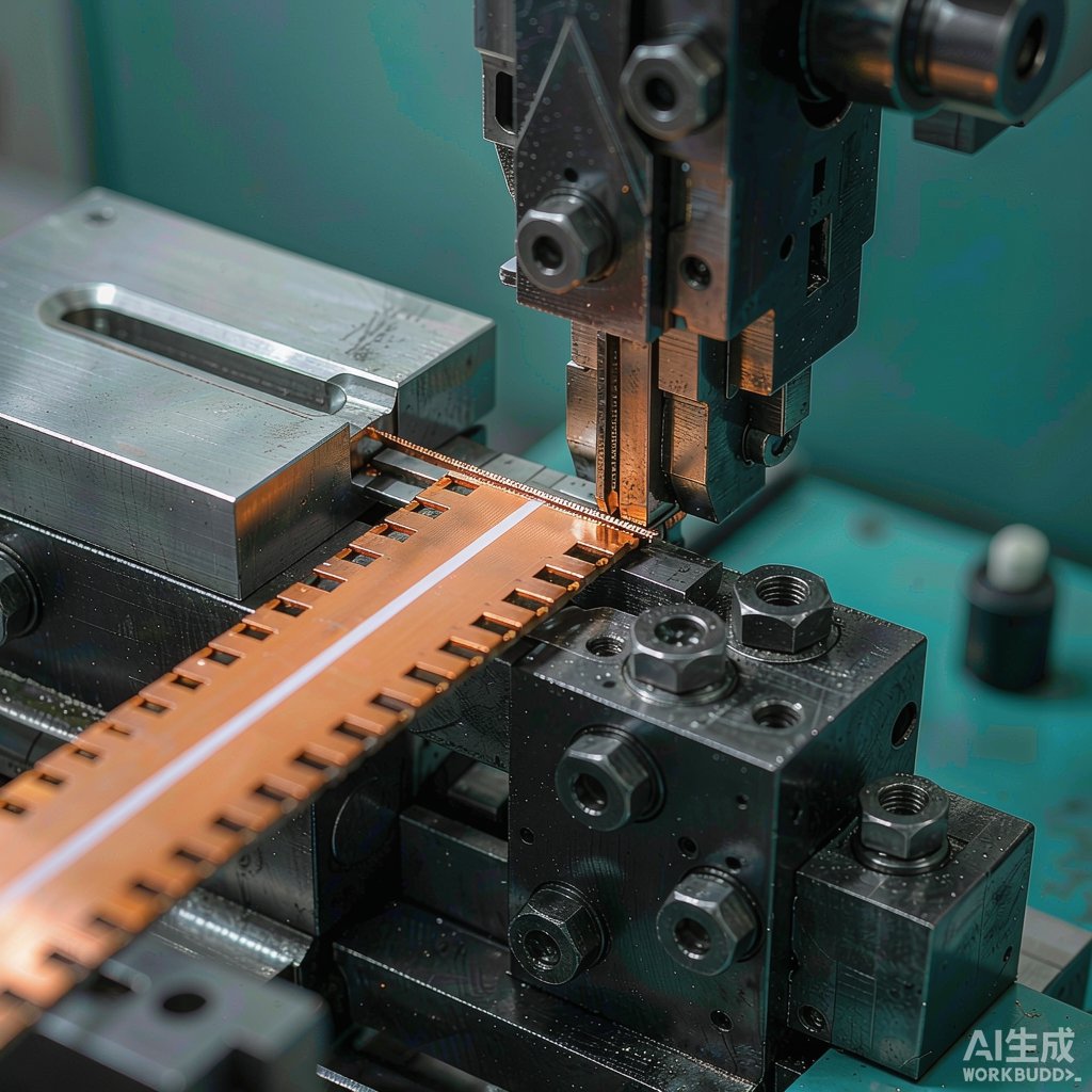
Fuse clips, spring contacts, shield can lids, battery tabs, and RF co
ector legs all begin as coils of copper or copper-alloy strip fed through a progressive stamping die. Every functional edge on those parts is a sheared edge, and the quality of that shear quietly decides whether the finished component plates cleanly, sits flat on the pad, and survives millions of insertion cycles. This guide explains how strip selection, slitting practice, and die parameters interact to control burrs on fine-pitch SMT contacts.
Why Edge Quality Decides Contact Performance
A sheared edge is never perfectly straight. Under the punch, the material passes through four zones: rollover where the edge curves inward, burnish where the material is smoothly cut, fracture where the break tears through, and finally the burr, a thin fin of displaced metal left at the exit side of the cut. The proportions of these zones shift with die clearance, tool sharpness, and strip temper.
- Plating uniformity: a burr shades the local current density during barrel or rack plating, leaving thin tin or nickel exactly where corrosion and fretting will start.
- Coplanarity: on a 0.3 mm pitch contact, a 20 µm burr is a seven percent height error that can hold the part above the pad and produce open joints at reflow.
- Insulation integrity: burrs pierce carrier tape pockets and thin dielectric films, causing jammed feeders and intermittent shorts.
- Contact resistance: a fractured edge oxidizes faster than a burnished one, raising interface resistance after thermal cycling.
Strip Temper and Microstructure Set the Baseline
Before any die is touched, the strip itself determines how cleanly it will shear. Full-hard tempers fracture cleanly with a small burr but risk cracking during forming; a
ealed tempers roll over deeply and produce long burrs. Most contact stampings use half-hard strip, which balances formability against edge quality.
Grain size matters as much as hardness. Fine-grain strip with grain size below about 0.030 mm shears with a straighter fracture line, while coarse grain tears irregularly and accelerates burr growth as tools wear. Alloys such as C5191 phosphor bronze and C17200 beryllium copper are supplied in tightly controlled tempers precisely because co
ector makers need predictable edge behavior at 0.2 to 0.5 mm thickness.
Slitting the Master Coil
Long before the progressive die runs, the wide master coil is slit into the strip width the die needs, and every slit edge becomes part of the final part geometry wherever the contact runs along the carrier edge. Poor slitting creates knife marks and work-hardened edges that propagate cracks during forming operations.
Clearance and Knife Condition
Slitting clearance typically runs five to ten percent of strip thickness per side for copper alloys. Too little clearance double-cuts and work-hardens the edge; too much rolls the edge over and leaves a heavy burr. Slitter knives must be resharpened on a scheduled interval measured in linear meters of strip, not when burrs happen to appear, because burr height grows continuously with knife wear.
Specifying the Slit-Edge Condition
Reputable service centers can supply strip with a specified edge condition: slit edge, deburred slit edge, or drawn-and-rounded edge. For contacts where the slit edge remains functional in the finished part, specifying a deburred or rounded edge at the mill removes an entire class of downstream problems for a modest price premium.
Die Clearance for Fine-Pitch Blanking
In blanking, burr height follows a U-shaped curve against clearance. Near zero clearance the punch plugs and tears the material; at excessive clearance the edge rolls over and the fracture line wanders. The optimum for copper alloys sits between those extremes.
- Soft copper (C11000, a
ealed): six to eight percent of material thickness per side.
- Half-hard brass and phosphor bronze: five to seven percent per side.
- Hard beryllium copper and stainless: four to six percent per side, with sharper tools to avoid insert chipping.
These values are starting points; the true optimum is found by sectioning sample edges and measuring the burnish-to-fracture ratio. A healthy shear shows roughly one third burnish zone and a fracture angle near ninety degrees to the strip surface.
Tool Steel, Coatings, and Maintenance
Punch and die inserts for copper contacts are usually made from D2 or powdered high-speed steel, often with TiCN or DLC coatings that reduce galling. This matters because galled copper smears onto the clearance surface and instantly raises burr height. Establish a regrind interval from measured burr data: when average burr height reaches half the acceptance limit, schedule a regrind rather than reacting to rejects.
Inspection and Acceptance Limits
Edge inspection belongs in the pressroom, not only in the laboratory. Common practice combines a bench microscope and portable profilometer for spot checks with an inline optical edge sca
er that measures burr height on every carrier edge at production speed.
Acceptance limits are usually expressed as a percentage of strip thickness. For contacts under 0.25 mm thick, a burr limit of ten percent of thickness is typical; precision RF contacts often tighten this to five percent. The measurement location matters — record the maximum burr along the edge, not the average, since a single local peak does the damage.
Post-Processes When Edges Must Be Perfect
Where design rules demand a radiused edge, for example on contacts that wipe against a mating surface, vibratory deburring with ceramic media can reduce burr height below five micrometers while rounding the fracture zone. The trade-offs are loss of sharp internal corners and the risk of media lodging in tight features, so parts are cleaned and re-inspected after tumbling. Electropolishing offers an alternative for high-volume precision parts, but it changes surface roughness and must be coordinated with the plating line.
Practical Sourcing Checklist
- Specify alloy, temper, and grain size on the strip certificate, not simply copper.
- State the required edge condition (slit, deburred slit, or rounded) and the maximum burr height.
- Request stamping trials at two clearance values before committing a die design.
- Agree on a burr measurement method, profilometer trace or calibrated micrograph, so supplier and customer report the same number.
Controlling edge quality is unglamorous work, but it is one of the few levers that improves plating, coplanarity, assembly yield, and contact life simultaneously. Treat the sheared edge as a specified surface with its own drawing tolerance, and most mystery contact failures disappear.



