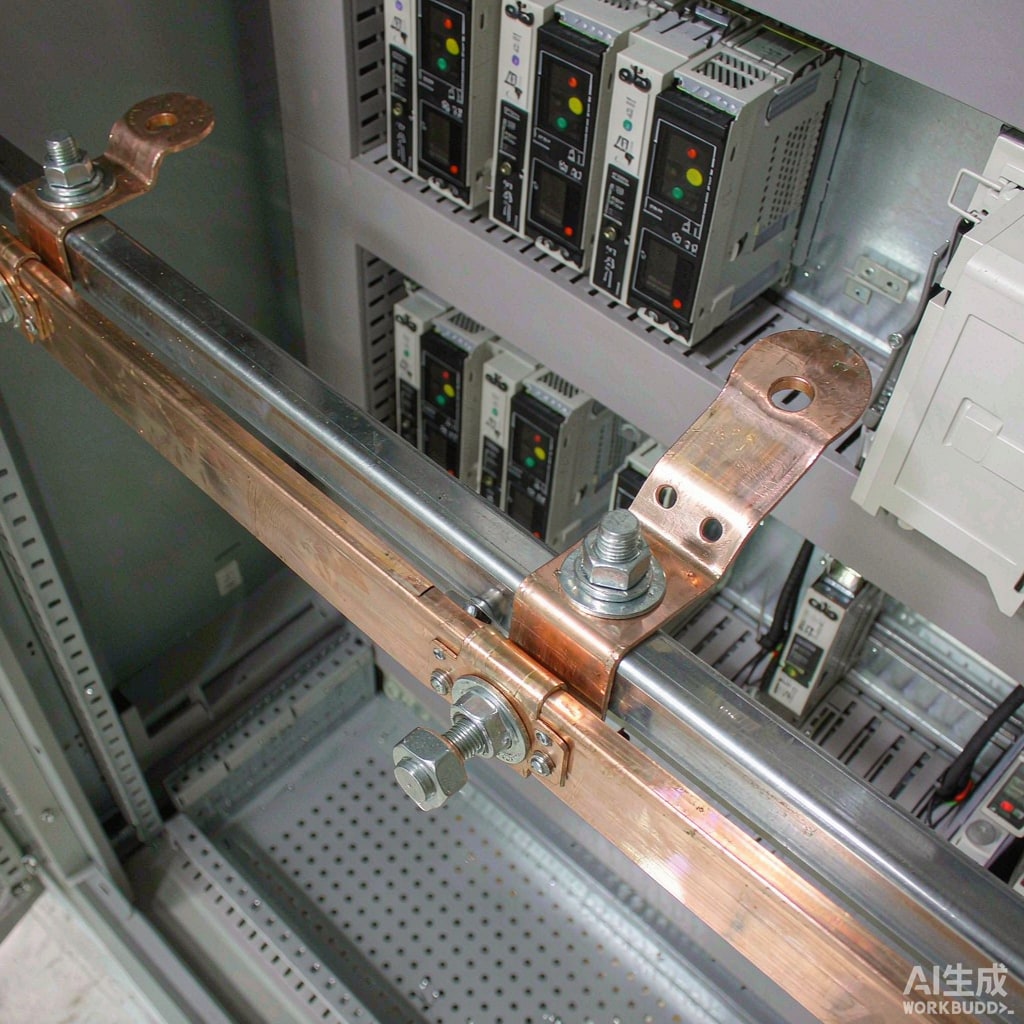
Every telecom cabinet, power shelf, and outdoor electronics enclosure depends on a quiet strip of metal that nobody photographs: the earthing busbar. Get it right and fault currents clear in milliseconds, surge protectors do their job, and EMI gaskets actually work. Get it wrong and you get intermittent alarms, corroded joints, and sites that fail acceptance. This guide covers how to specify copper strip for earthing busbars and ground straps in telecom and industrial electronics cabinets.
Why Earthing Busbars Matter in Electronics Cabinets
An earthing busbar does three jobs. First, it provides a low-impedance fault current path so that protective devices trip quickly during a short circuit. Second, it bonds surge protective devices to a common reference so lightning and switching transients have somewhere to go. Third, it anchors the EMI ground reference: shield can pads, gasket flanges, and cable shield terminations all tie back to this bar. A busbar with high resistance or a corroded joint undermines all three at once.
Alloy and Temper Selection
For earthing duty, electrical conductivity beats mechanical strength. Electrolytic tough pitch copper, C11000, at about 100 percent IACS conductivity is the default choice for busbars and ground straps. Where the strip must hold a form, for example a formed L-bracket or a punched mounting tab, a half-hard temper gives enough stiffness to keep the shape after bending without significantly reducing conductivity. Avoid brass for earthing hardware; at roughly 28 percent IACS it wastes cross-section, and its zinc content can dezincify in humid outdoor environments.
Bare, Ti
ed, or Plated Strip
Bare copper is acceptable only in clean, dry, indoor cabinets with consistent torque maintenance. For outdoor and coastal sites, hot-dip or electro-ti
ed copper strip is the standard: tin resists oxide growth, keeps contact resistance low and stable across years, and is compatible with soldered as well as bolted co
ections. Nickel plating suits high-temperature compartments near rectifiers, where tin intermetallic growth would otherwise become a concern over long service life.
Sizing the Strip: Fault Current and Surge Duty
Size the busbar for the worst credible current, not the average load. For fault current, use the adiabatic relationship: the required cross-section scales with fault current multiplied by the square root of clearing time. A distribution cabinet that must carry a 10 kA prospective fault for 100 milliseconds needs far more copper than a 50 millisecond clearing scenario, and the protection coordination study, not guesswork, defines that time. For surge duty, size according to the lightning protection zone concept: bonding conductors from surge protective devices to the busbar should handle the partial lightning current assigned by the site risk assessment, and standards such as IEC 62305 provide the cross-section tables.
Practical Dimensions and Forming Rules
Most telecom cabinets use strip in the range of 3 to 6 millimeters thick and 20 to 50 millimeters wide. Keep the width-to-thickness ratio moderate so the strip stays flat against mounting surfaces. When punching terminal holes, maintain an edge distance of at least 1.5 times the hole diameter and a pitch between holes of at least 2 times, or the strip will neck and tear during forming. Deburr both faces after punching; a raised burr under a lug washer is a classic high-resistance joint that passes factory inspection and fails two years later.
Bonding Practices That Actually Hold
The busbar is only as good as its co
ections. Bolt lugs directly to the bar with Belleville spring washers or captive flanged hardware so that the joint stays compressed through thermal cycling. Route ground straps short and wide: inductance, not resistance, dominates the impedance of a strap at surge frequencies, so a wide strip pressed flat against the cabinet wall outperforms a thin wire run around the corner. Where a cabinet bonds to a rack or plinth, use braided or flat straps rated for the job and keep the path under 300 millimeters wherever practical.
Managing Bimetallic Joints
Copper-to-aluminum and copper-to-steel junctions are the corrosion hot spots in any earthing system. Use ti
ed interfaces, apply an oxide-inhibiting compound, and where the electrochemical potential difference is large, insert a bimetallic transition washer or a stainless steel intermediary so the copper and aluminum never touch directly. This is the single most common cause of rising earth resistance found during site audits in humid coastal regions.
Corrosion Control and Inspection
Specify contact surfaces free of oxides at assembly: wipe with a suitable solvent, brighten if needed, and torque to the hardware manufacturer value within minutes of cleaning. For outdoor cabinets, inspect earthing joints a
ually, and after any notable storm season, using a four-wire milliohm meter across each joint. A healthy bolted copper-to-ti
ed-lug joint measures in single-digit milliohms; anything drifting upward by an order of magnitude indicates oxide growth, loss of clamping force, or galvanic attack underneath the hardware.
Acceptance Checklist for Buyers
When sourcing earthing busbars and straps, ask suppliers for: material certification confirming C11000 or equivalent with conductivity data; plating thickness records for tin or nickel finishes; hole pattern drawings with edge distances; and torque tables for the supplied hardware. Then verify on receipt that the strip is flat, holes are burr-free, and the plating shows no blistering. These five checks catch the defects that later become the site problems nobody can explain.



