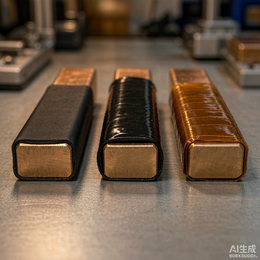
An uninsulated copper busbar in a power distribution assembly is a fault waiting for a wrench. Yet specifying the insulation is often left to the last minute, when the mechanical envelope is already frozen and someone asks for “something black, 0.3 mm thick.” That decision quietly sets the dielectric margin, the thermal ceiling, and the field-failure mode of the whole assembly. This guide compares the three insulation systems most commonly applied to copper strip busbars in SMT power boards, battery packs, and switchgear sub-assemblies.
What Busbar Insulation Actually Has to Do
A busbar coating has five concurrent jobs, and most specifications only test two of them.
The five requirements
- Dielectric isolation between phases, or between a live bar and a grounded chassis.
- Cut-through resistance against burrs, screw threads, and sheet-metal edges during assembly.
- Thermal endurance at the bar’s real continuous temperature, not the ambient in the spec sheet.
- Mechanical stability through thermal cycling and vibration — no flaking, no cracking at the bend radius.
- Chemical tolerance to flux, IPA, and cleaning agents on the assembly line.
Copper’s thermal conductivity works against you: a bar carrying 400 A can run at 90–110 °C while ambient is 40 °C. Insulation rated “105 °C” will age badly there.
Powder Coating: The Volume Default
Electrostatic powder coating with an epoxy or polyester-epoxy resin is the standard for formed busbars produced in quantity. Typical builds run 60–150 µm per side, applied after stamping and forming so the coating follows the final geometry.
Where powder wins
Uniform coverage over complex shapes, including the i
er corner of a 90° bend where tape wrinkles. Adhesion is excellent on properly prepared copper — a chromate-free conversion pretreatment is essential, because powder on bare, oily copper delaminates within a few thermal cycles. A pinhole-free 100 µm epoxy build gives 3–6 kV dielectric strength, far above the 1–2 kV most low-voltage busbars need.
Where powder fails
Masking is the hidden cost. Every contact pad, bolt hole, and threaded insert must be masked before coating. Masking plugs, removal labour, and rework on over-spray drive cost quickly. Powder also has poor flexibility: at a 2 mm bend radius on a 1.5 mm bar, a 150 µm epoxy film can crack microscopically, creating a moisture path that will not show up until field failure. Specify a flexible polyester-epoxy hybrid, or coat after forming and never form the coated part.
A practical quality gate: bend one coated sample per lot 180° around a mandrel and inspect at 10× magnification. Crazing at the bend is a leading indicator of batch cure problems.
Heat-Shrink Tubing: Repair and Low-Volume
Cross-linked polyolefin heat-shrink, typically 2:1 or 3:1 shrink ratio, is the practical answer for prototypes, repairs, and low-volume builds. A 1.5 mm wall of cross-linked polyolefin gives roughly 10–15 kV/mm dielectric strength and continuous rating of 105–135 °C depending on the grade.
Strengths
No masking — slide the tube on, shrink it, done. Very high cut-through resistance because the wall is thick and cross-linked. Easy field repair. Adhesive-lined versions give a moisture seal at the ends. Cost per metre is low for small quantities.
Real limitations
Shrink tubing is straight-line only. Every bend, bolt hole, and terminal transition becomes a manual operation, and the consistency of a hand-shrunk joint depends on the operator’s heat gun technique. Over-shrinking thins the wall; under-shrinking leaves an air gap that reduces dielectric performance and allows vibration wear. On a long bar, the tube also traps air that expands on heating and can creep the tubing off the end. Use adhesive-lined tubing and a proper end seal if the bar sees thermal cycling above 100 °C.
Polyimide and PET Tape: The Compromise
Polyimide (Kapton-type) film tape at 25–75 µm, or thicker polyester (PET) tape at 50–130 µm, wrapped 50% overlap, is the working solution for small runs, angled geometries, and rework.
Strengths
Extremely high temperature rating — polyimide is used up to 260 °C continuous, which suits bars near a soldering or welding operation. Thin, so it fits tight envelopes. Wrap-on application means no masking and no tooling. Silicone adhesive versions survive reflow-adjacent temperatures.
The catch
Dielectric strength per layer is only about 100–150 V/µm for polyimide, so a single 25 µm layer is worth roughly 3–4 kV — acceptable, but a wrap with gaps or lifted edges is worth far less. Cut-through resistance is poor: a burr or screw thread will puncture tape. Adhesive can also migrate or leave residue at high temperature, and acetate or PET tapes are not suitable above 105 °C. Tape is the right answer for geometry and small quantities, not for a production busbar that must survive 10 years of vibration.
Side-by-Side Comparison
Decision matrix
- Production volume above 5,000 pieces, straight or simple formed bar: powder coating. Best cost per part, best uniformity.
- Complex geometry, prototypes, or fewer than 500 pieces: heat-shrink tubing. No tooling, no masking.
- Bar adjacent to a soldering or welding process, or an angled small run: polyimide tape.
- High-vibration battery pack with bolt-on terminals: heat-shrink over the bar body plus a moulded end cap; tape will fretting-wear through.
- 90 °C continuous, 150 °C excursion, coastal humidity: flexible polyester-epoxy powder, 100 µm minimum, with conversion pretreatment.
Specification Checklist for Procurement
Write these into the purchase order and the disputes at incoming inspection disappear.
What to put on the drawing
- Insulation type and nominal build thickness, per side, with tolerance.
- Dielectric test voltage and duration (for example 2.5 kV AC, 60 s, no breakdown).
- Continuous operating temperature and excursion limit.
- Cut-through requirement: reference a needle or edge test method rather than saying “robust.”
- Copper surface preparation before coating — conversion coating or mechanical abrasion, no bare oily copper.
- Masked zones defined by dimension, not by “all contact areas.”
- Bend radius minimum for the coated part, and whether forming precedes or follows coating.
- Flammability rating, typically UL94 V-0 for enclosure-mounted bars.
Add a first-article report with the dielectric result and film thickness measured by cross-section at three points. For tropical destinations, add 500 h damp heat at 40 °C / 93% RH followed by a dielectric test — that single test catches most pretreatment failures.
The Cost View Most Buyers Miss
Price per metre alone misleads. Powder coating carries masking labour, heat-shrink carries assembly labour, tape carries the most labour of all. Compare total landed cost of the finished bar including scrap and rework. Powder wins on volume, heat-shrink on simplicity, tape on geometry — each loses where the others win. Choose the failure mode you can live with and specify around it.
Frequently Missed Details
Two details repeatedly cause field returns. First, edge coverage: slit copper strip has a slightly rounded, burred edge that receives less coating than the flat faces, and that edge is exactly where a ground strap rubs. Specify edge coverage explicitly and inspect a cross-section. Second, coating over the bend: a bend concentrates stress in the film, so ageing accelerates there. If the bar must bend after coating, specify a flexible resin and a 180° bend test on every lot. Get these two right and insulated copper strip busbars become boring — which is exactly what a power distribution assembly should be.



