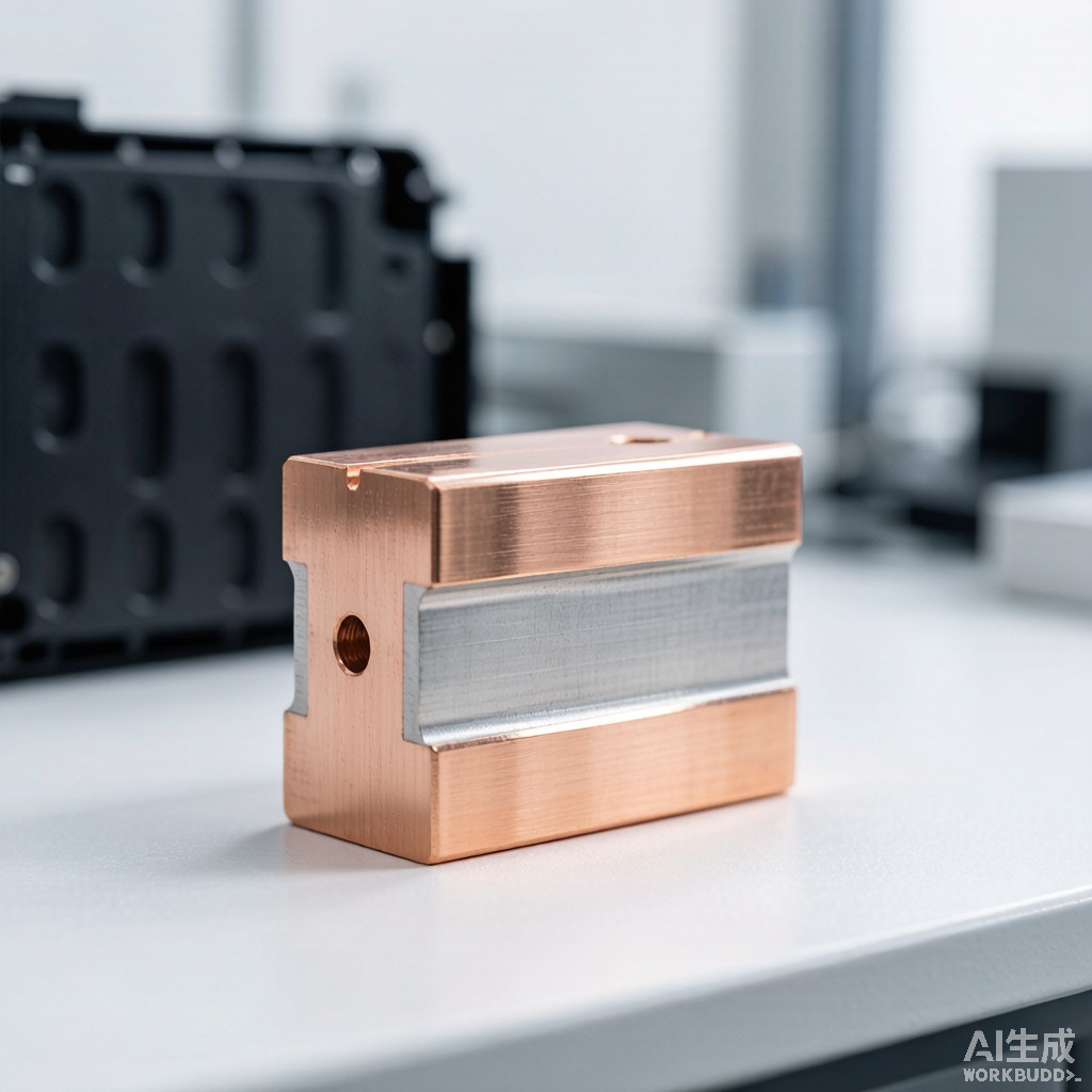
Electric vehicle traction battery packs operate at 400V (legacy) or 800V (modern fast-charge) architecture with continuous current ranging from 200A to 600A per busbar segment. Solid C11000 electrolytic tough pitch (ETP) copper busbars have dominated this application due to 100% IACS conductivity and proven reliability, but at 8.96 g/cm³ density they add 15-25 kg to a typical 100 kWh pack, reducing vehicle range by 1-2% and increasing unsprung mass at the chassis floor. Copper-clad aluminum (CCA) bimetal busbar—also called copper-aluminum transition busbar or Al-clad Cu strip—combines an aluminum core (1350-O or 6063 alloy, 2.70 g/cm³) with a 10-25% thickness ratio of bonded copper cladding, achieving 60-75% IACS effective conductivity at 40-50% weight reduction. This article examines the materials engineering, ASTM B566 cladding metallurgy, galvanic corrosion mitigation, ultrasonic welding process control, and design trade-offs for CCA busbars in 800V EV battery pack applications.
Why CCA Busbar for EV Battery Pack
Mass-Driven Range Improvement
Vehicle efficiency analysis shows that every 100 kg of mass reduction in a battery-electric vehicle extends WLTP range by approximately 6-10 km in the urban cycle and 3-5 km in the highway cycle, depending on baseline vehicle weight. For a typical 100 kWh pack with 18-24 busbar segments at 3-5 kg each in solid copper, switching to CCA saves 8-15 kg per pack, contributing 0.5-1.0% range extension. The weight reduction is most valuable when concentrated low in the chassis, where it lowers the center of gravity and improves handling response—particularly relevant for performance EVs and sport utility vehicles targeting sub-5 second 0-100 km/h acceleration.
Conductivity-to-Weight vs Pure Copper
Volume resistivity, density, and conductivity-to-density ratio (specific conductivity) determine busbar selection:
| Material | Density (g/cm³) | Volume Resistivity (µΩ·cm) | Conductivity (% IACS) | Specific Conductivity (kA·m/kg) |
|---|---|---|---|---|
| C11000 ETP Copper (a
ealed) |
8.96 | 1.724 | 100 | 18.7 |
| 1350-O Aluminum (99.5% Al, O temper) | 2.70 | 2.83 | 61 | 20.6 |
| 6063-T6 Aluminum (Mg-Si alloy) | 2.70 | 3.10 | 55 | 18.6 |
| CCA 20% Cu / 80% Al (typical) | 3.96 | 2.45 | 70 | 17.7 |
| CCA 30% Cu / 70% Al (premium) | 4.59 | 2.10 | 82 | 17.9 |
| CCA 40% Cu / 60% Al (high-Cu) | 5.20 | 1.93 | 89 | 17.1 |
At a 20% copper cladding ratio (typical production configuration), CCA delivers 70% IACS effective conductivity, which is more than adequate for 400A continuous current at 800V architecture, given that 2-3× over-spec current capacity is common in OEM design margin. The specific conductivity (kA·m/kg) is comparable to pure copper within 5%, confirming that the mass saving does not penalize current-carrying capacity per unit mass.
Cladding Interface Metallurgy
ASTM B566 Roll-Bonding Process
CCA busbar is manufactured by hot roll-bonding per ASTM B566, where a copper strip (typically 0.5-3.0 mm thick) is pressure-bonded to an aluminum core (3-10 mm thick) at 400-500°C with 30-60% area reduction in a single pass. The critical interface layer is 1-5 µm thick and forms a Cu-Al intermetallic compound (IMC) of CuAl₂ (θ phase) and Cu₉Al₄ (γ phase). Excessive IMC thickness (>10 µm) embrittles the joint and reduces fatigue life; insufficient IMC (<0.5 µm) creates a mechanically weak bond that delaminates under thermal cycling. Production-grade CCA targets 2-4 µm IMC thickness verified by cross-section metallography per ASTM E3 and E1351.
Bond Strength & Peel Test
Bond strength is qualified by the 180° peel test per ASTM B547 (standard for aluminum-clad steel, applicable to CCA by analogy), with a 10-25 mm wide strip peeled at 50 mm/min crosshead speed. Production acceptance criteria typically require ≥35 N/mm (200 lbf/in) peel strength, with automotive-grade CCA targeting ≥55 N/mm (315 lbf/in). Heat-affected zone (HAZ) softening at the bond interface during subsequent laser welding or ultrasonic welding operations can reduce local bond strength by 15-25%, so OEM welding process qualification must include post-weld peel testing on production-representative coupons.
Galvanic Corrosion Mitigation
Why Exposed Cu-Al Interface is a Reliability Risk
Copper and aluminum form a galvanic couple with 0.65-0.75V potential difference in neutral 3.5% NaCl (ASTM B117 salt spray) electrolyte, ranking aluminum as the sacrificial anode. Without protection, exposed CCA edges in battery packs—particularly at the busbar-to-cell tab laser weld fillet where bare aluminum is exposed—corrode at 80-150 µm/year in marine or tropical climates, leading to open-circuit failures within 5-7 years. The automotive industry has converged on two primary mitigation strategies:
| Strategy | Description | Cost Impact | Service Life Extension |
|---|---|---|---|
| Edge overmolding | Polyamide or PPS plastic mold encapsulating exposed Cu-Al transition zone | $0.50-1.20/busbar | +8-12 years |
| E-coat + edge seal | Cathodic electrodeposition coating with additional UV-cure edge sealant | $0.30-0.80/busbar | +5-8 years |
| Tin plating on Cu + epoxy | 3-8 µm matte tin over copper side; epoxy edge cap | $0.20-0.50/busbar | +4-7 years |
| Full submersion in dielectric | Busbar fully potted in polyurethane or epoxy gel | $1.50-3.00/busbar | +12-15 years |
Coating Stack for Tropical Deployment
For Southeast Asia automotive deployment, a 3-layer coating stack is recommended: (1) zinc chromate or trivalent chromium passivation on aluminum side; (2) 8-15 µm electroless nickel (mid-phosphorus 6-9% P) over both Cu and Al for galvanic isolation; (3) 25-40 µm epoxy powder coat (UL 94 V-0 rated) for mechanical and moisture barrier. This stack passes 2,000-hour ASTM B117 neutral salt spray and 1,000-hour ASTM G85 cyclic prohesion testing, supporting 15-year service life under hood or battery pack operating conditions.
Welding & Termination Process
Ultrasonic Welding of Cell Tabs to CCA
Pouch cell or prismatic cell aluminum tabs (typically 0.2-0.3 mm 1050-O or 3003-O aluminum) are joined to the CCA busbar aluminum side by ultrasonic metal welding (20-40 kHz, 1.5-3.0 kN weld force, 0.5-1.5 second weld time, 30-80 µm amplitude). The weld nugget reaches 280-340°C at the interface, causing localized HAZ softening but no melting (solid-state weld). Peel strength of 60-120 N/cm is typical for 0.2 mm tab to 5 mm CCA. Copper-side terminations to high-voltage co
ectors or PCB busbars use laser welding (fiber laser, 1-3 kW peak, 1-4 second pulse) or resistance spot welding with copper-compatible electrodes.
Bimetallic Transition Joint
Where pure copper cables (e.g., to motor inverter) meet CCA busbar segments, a bimetallic transition joint—either friction-welded Cu-Al stub per AWS D17.1 or explosion-bonded transition plate per ASTM B432—is inserted to avoid direct Cu-Al galvanic coupling in the cable termination. These transitions are 10-15 mm long and rated 600A continuous with 10°C temperature rise at the joint. OEM harness drawings specify the transition location within 50-100 mm of the high-voltage junction box to localize the dissimilar metal boundary to a single inspectable location.
Thermal Management & Current Capacity
Steady-State Current Rating
For a 5 mm × 30 mm CCA busbar (20% Cu / 80% Al) in free air at 25°C ambient, the steady-state ampacity is approximately 540A at 30°C temperature rise and 720A at 50°C rise. By comparison, a 5 mm × 30 mm solid C11000 copper busbar of the same dimensions carries 760A at 30°C rise and 1,030A at 50°C rise. The 25-30% derating is acceptable for most EV applications because (a) battery packs operate in enclosed housings with conductive cooling plates that limit ambient to 50-60°C, (b) peak current events are <30 seconds duration and the thermal mass of the busbar (3-5× the energy storage of copper per °C) absorbs transients effectively, and (c) design margin targets 60-70% loading for continuous duty.
Thermal Cycling Reliability
EV battery packs experience 30-50 thermal cycles per day (charge-discharge, ambient swing, fast-charge thermal load), accumulating 30,000-100,000 cycles over service life. CTE mismatch between copper (16.5 ppm/°C) and aluminum (23.1 ppm/°C) creates 1,500-3,000 microstrain at the cladding interface per 100°C swing, with potential for fatigue crack initiation in the IMC layer. Production-grade CCA busbars are validated to 5,000 thermal shock cycles (-40°C to +85°C, 30 min dwell, 5 min transfer) per IEC 60068-2-14 without bond delamination or >20% resistance increase. Premium automotive-grade CCA targets 10,000 cycles with the same acceptance criteria.
Cost-Benefit Analysis
Material Cost Comparison (2026 SE Asia pricing)
Material cost per kg for EV-grade busbar stock: solid C11000 copper at $9.20-10.50/kg LME-based, versus CCA 20% Cu bimetal at $5.80-7.20/kg. A 5 mm × 30 mm × 800 mm busbar weighs 1.07 kg in copper and 0.47 kg in CCA—a 56% mass reduction. The material cost saving per busbar is approximately $4.50-6.00, and across a 24-segment pack the saving is $108-144 per vehicle. When accounting for additional edge overmolding and enhanced coating ($0.80-1.20 per busbar), the net saving is $88-120 per pack, equivalent to $44-60 per kWh at 2 kWh-per-busbar-segment density.
Supply Chain Considerations
CCA bimetal busbar production is concentrated in a small number of qualified mills (American Clad Metals, Kaiser Aluminum Clad Products, Henan Mingtai Al-Clad, Shanghai Metal Corporation), with lead times of 6-10 weeks for custom cross-sections. Solid copper busbar stock is more widely available from 50+ mills globally with 3-5 week lead times. Southeast Asia (Thailand, Vietnam, Malaysia) has limited domestic CCA busbar production, making import logistics and port handling an additional consideration for OEMs sourcing locally. Minimum order quantities for custom CCA ratios are typically 2-5 metric tons, suitable for production runs of 5,000-15,000 packs.
Conclusion
CCA bimetal busbar provides 60-75% IACS conductivity at 40-50% weight reduction versus solid C11000 copper, with material cost savings of $88-120 per EV battery pack. The 800V architecture with 400A continuous rating is well within CCA ampacity, and ASTM B566-compliant roll-bonding with 2-4 µm IMC thickness provides reliable service over 15-year automotive deployment. Edge overmolding or full epoxy potting mitigates galvanic corrosion at exposed Cu-Al interfaces, and ultrasonic welding of aluminum cell tabs to the Al side eliminates additional dissimilar metal transitions in the pack. The technology is mature, qualified by major EV OEMs (Tesla, BYD, Hyundai E-GMP, Volkswagen MEB), and represents one of the most cost-effective lightweighting strategies for 800V battery pack interco
ects in the 2026-2030 model cycle.



