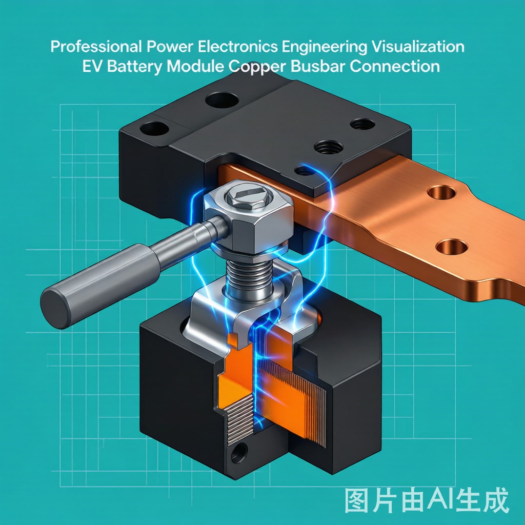
Introduction: Why a Bolt Joint Becomes a Reliability Limit
In electric vehicle battery packs, stationary energy storage systems, and high-current power distribution units, copper busbars carry hundreds of amps between battery cells, modules, contactors, and inverters. A typical 10 mm × 50 mm × 200 mm tin-plated copper busbar operating at 400 A DC continuous produces roughly 30 W of resistive heating at the joint—not in the busbar body, but at the bolted interface where two conductive surfaces meet. Over thousands of thermal cycles, the bolted joint becomes the most failure-prone element in the entire power distribution chain. This article examines the physics of bolted busbar co
ections, the design parameters that govern contact resistance stability, and the engineering practices that deliver decades of reliable service in harsh automotive and industrial environments.
Contact Resistance: The Physics of Metal-to-Metal Contact
Constriction Resistance and Asperity Contact
When two metal surfaces are brought into contact under bolt preload, they do not touch across their full apparent area. Microscopic surface asperities—peaks and valleys created by machining, stamping, or plating—make the actual metallic contact at discrete spots that may total only 1–5% of the apparent area. Current must ‘constrict’ through these tiny contact spots, creating a localized constriction resistance (Rc) that is many times higher than the bulk resistance of an equivalent solid conductor. The classic Holm equation captures this relationship:
Rc = ρ / (2 × a × n)
Where ρ is the resistivity of the softer contact metal, a is the radius of a single asperity contact spot, and n is the number of asperity contacts. As bolt preload increases, asperities deform plastically, increasing both a and n, thereby reducing Rc. However, this relationship is non-linear: doubling the preload typically reduces Rc by only 20–30% because plastic deformation quickly reaches a yield plateau.
Film Resistance and Surface Finish
The second component of total joint resistance is the film resistance (Rf) created by oxide layers, plating, and adsorbed contamination on the contact surfaces. Bare copper rapidly forms a Cu2O/CuO oxide layer that is semi-conductive but adds 0.5–5 mΩ per interface. Tin plating (Sn or Sn/Ag) reduces Rf dramatically to 0.05–0.2 mΩ per interface but introduces a long-term reliability concern discussed in the fretting corrosion section below. Silver plating (Ag) provides the lowest Rf at 0.02–0.1 mΩ but is rarely used in cost-sensitive EV applications.
| Surface Finish | Rf per Interface (mΩ) | Stability in Humid Environment | Cost Index | Typical Application |
|---|---|---|---|---|
| Bare copper, freshly cleaned | 0.3–1.0 | Poor (oxidation in days) | 1.0× | Not recommended |
| Bare copper, inhibited (BTA) | 0.5–2.0 | Fair (6–12 months) | 1.1× | Industrial enclosures |
| Tin-plated (3–8 μm matte Sn) | 0.1–0.3 | Good (oxidation limited) | 1.3× | EV battery packs (most common) |
| Bright tin-plated (3–5 μm) | 0.05–0.2 | Fair (whisker risk) | 1.4× | Consumer electronics |
| Silver-plated (3–5 μm) | 0.02–0.1 | Good (tarnish non-conductive only) | 3.5× | Aerospace, military |
| Nickel-plated (3–5 μm) | 0.5–1.5 | Excellent | 1.5× | High-temperature applications |
Bolt Torque, Preload, and the Critical Joint Design
Calculating Required Preload
The required bolt preload (Fp) is governed by the need to maintain contact pressure above a threshold that prevents micro-motion and fretting, while staying below the bolt yield strength to avoid plastic deformation. For a M8 steel bolt (8.8 grade), the typical preload target is 65–75% of the bolt’s proof load:
Fp = 0.7 × σproof × As
For an M8 8.8 bolt: σproof ≈ 600 MPa, As ≈ 36.6 mm² → Fp ≈ 15.4 kN. The corresponding torque is calculated as:
T = K × Fp × d
Where K is the nut factor (typically 0.20–0.30 for steel-on-steel with light oil, 0.10–0.15 for PTFE-coated or zinc-plated fasteners) and d is the bolt nominal diameter. For K = 0.20, M8 bolt: T ≈ 0.20 × 15,400 N × 8 mm = 24.6 Nm. Most automotive busbar specifications call for 18–25 Nm on M8 joints.
Torque-Tension Relationship and Scatter
The single largest source of joint variation is the scatter in the nut factor K, which is sensitive to surface finish, lubrication, thread cleanliness, and tightening speed. A typical K variation of ±0.04 across a population of nominally-identical fasteners produces preload scatter of ±20%, even with perfect torque control. This is why critical joints in EV battery packs increasingly use torque-angle controlled tightening or stretch-controlled bolting rather than pure torque control. The angle method tightens to a snug position, then rotates the nut a controlled additional angle (typically 60–90° for M8), which directly correlates to bolt elongation and therefore preload.
Fretting Corrosion: The Silent Killer of Busbar Joints
Mechanism of Fretting Degradation
Tin-plated copper busbars in EV battery packs operate in a vibration-rich, thermally-cycling environment. The battery pack temperature swings from -40°C (cold soak) to +85°C (peak operation) every operating day, and engine bay or chassis vibration continuously excites the bolted joint at frequencies from 10 Hz to 2000 Hz. The differential thermal expansion between the copper busbar (CTE 17 ppm/°C) and the aluminum or steel battery housing (CTE 23–12 ppm/°C) creates micro-slip at the joint interface on every thermal cycle. This micro-slip—typically 5–50 μm—is too small to detect visually but is sufficient to fracture the brittle tin oxide layer formed between cycles, exposing fresh tin to oxidation. The cycle of sliding, oxidation, sliding accumulates as fretting debris—mixed Sn/SnO2/Cu particles—that progressively increases contact resistance.
Quantifying Fretting Resistance Growth
Fretting corrosion causes contact resistance to grow following a logarithmic or power-law relationship with cycle count:
R(t) = R0 × (1 + α × log(N))
Where R0 is initial contact resistance, N is cycle count, and α is a material-specific fretting coefficient. For tin-plated copper, α typically ranges from 0.5 to 2.0, meaning resistance can grow 30–100% over 1000 thermal cycles. EV manufacturers target less than 50% resistance growth over 3000 thermal cycles (-40°C to +85°C) to qualify a busbar design, per the USCAR-11 specification.
Fretting Mitigation Strategies
- Higher bolt preload (25–30 Nm on M8): Reduces micro-slip amplitude but increases bolt stress and reduces fatigue life of the bolt itself. Trade-off must be managed.
- Conductive grease (e.g., Molykote Dx, Nye Nyogel): Fills asperity valleys, prevents oxygen ingress, reduces micro-slip. Adds 50–100 μm thickness which must be accounted for in joint stack-up.
- Sn/Ag or Sn/Pb plating: Replaces pure Sn with alloys less prone to oxide growth, reducing α by 40–60%.
- Mechanical locks (Nord-Lock, Belleville washers): Maintain preload against vibration-induced bolt loosening. Especially important for chassis-mounted packs.
- Adhesive thread-locking (Loctite 243, 263): Secondary defense against vibration loosening. Must be selected for the temperature range.
- Laser-textured contact surfaces: Emerging technology that creates controlled micro-patterns to trap wear debris and maintain conductive paths.
Thermal Cycling and Joint Stack-Up Management
CTE Mismatch Compensation
The differential expansion between copper (17 ppm/°C), aluminum (23 ppm/°C), and the FR-4 or metallic busbar carrier creates mechanical stress at every thermal cycle. For a 200 mm busbar spa
ing -40°C to +85°C, the differential expansion is:
ΔL = L × ΔT × ΔCTE = 200 mm × 125°C × 6 ppm/°C = 0.15 mm
This 150 μm expansion must be absorbed by the joint stack-up (bolt elongation, washer compression, plate flexure) without exceeding the elastic limit of any component. Excessive stack-up compliance allows the joint to slip and fret; insufficient compliance causes bolt overload and fatigue. Spring washers (Belleville or wave) are commonly used to provide 50–200 μm of elastic compliance while maintaining preload.
Joint Stack-Up Best Practice
| Layer | Material | Thickness (mm) | Function |
|---|---|---|---|
| Bolt head | Steel 8.8 | 8 | Clamping force application |
| Flat washer | Steel, zinc-plated | 1.5 | Load distribution, friction reduction |
| Belleville washer | Spring steel | 1.5 (deflection 0.2 mm) | Elastic compliance, vibration damping |
| Copper busbar | C11000 ETP, 10 mm thick | 10 | Current conduction |
| Battery terminal | Aluminum A380 die-cast, Sn-plated | 15 | Cell co
ection |
| Flat washer | Steel, zinc-plated | 1.5 | Load distribution |
| Nut | Steel 8.8 with nylon insert | 8 | Clamping force retention |
Conclusion: The Busbar Joint Is a Designed System
The copper busbar bolted joint is a precision electromechanical system that requires as much engineering attention as the semiconductor switching devices it supports. A 1°C temperature rise at a poorly-designed joint reduces battery pack efficiency by 0.5% and accelerates fretting corrosion by 2–3×. Conversely, a properly designed joint with correct bolt preload, surface finish, fretting mitigation, and stack-up management delivers the full 10–15 year service life of an EV battery pack with negligible resistance growth. The busbar itself is commodity copper; the joint is engineering.



