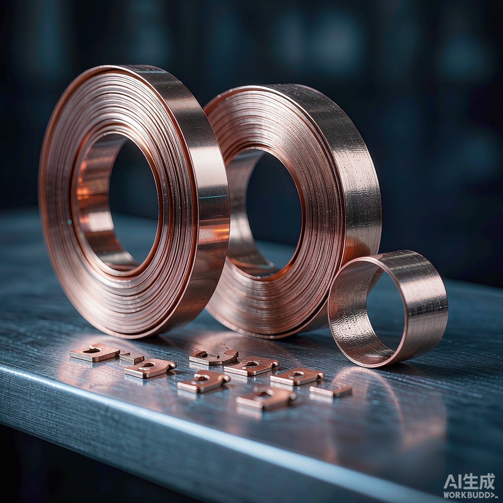
Two suppliers quote the same specification: 0.20 mm C11000 copper strip, H02 temper, 100 percent IACS. The prices differ by six percent, and the parts that come off your progressive die do not perform the same. The difference usually traces back to a question that never appears on a purchase order: was the strip continuously cast and rolled in line, or was it cast as a slab, homogenised, hot rolled, cold rolled, a
ealed and skin passed?
Both routes are legitimate and both can produce excellent SMT stamped contacts. But they carry different grain structures, oxygen levels, thickness control and cost structures, and each of those translates into bend formability, burr height and plating adhesion.
The Two Production Routes
Wrought route: slab casting, hot rolling, cold rolling
Conventional wrought strip starts with a semi-continuous vertical DC cast slab 150 to 300 mm thick. The slab is homogenised at 800 to 900 degrees C to dissolve segregation, hot rolled to 15 to 25 mm, then cold rolled with intermediate a
eals to final gauge, finished by a one to three percent skin pass that controls flatness, surface and yield strength. Because each coil is cold worked and a
ealed separately, the producer controls grain size and mechanical properties coil by coil and can certify them.
Continuous cast and rolling: molten to coil in one line
Continuous cast and rolling (CCR) pours molten copper onto a wheel or twin-belt caster, solidifies it into a bar of 2000 to 5000 square millimetres, and rolls it in line to 8 mm rod or, in some plants, directly toward strip gauge. Sheet thickness strip is then cold rolled and a
ealed conventionally. Solidification cooling rates are far higher than in a DC slab, so the as-cast dendrite arm spacing is finer, segregation is reduced, and homogenisation can be shortened or skipped.
What that does to grain structure
DC slab castings begin with coarse columnar grains that must be broken down by homogenisation and hot rolling; if homogenisation is short, banding survives into the finished strip and shows up later as directional bend performance. CCR strip starts finer and more equiaxed, giving more isotropic forming behaviour, at the price of a slightly higher risk of centreline porosity if casting temperature and gas control drift. Porosity is invisible on the coil surface and appears only when a stamped contact fractures on a bend line.
Oxygen Content Is the Hidden Variable
Standard electrolytic tough pitch copper, C11000, contains 0.02 to 0.04 percent oxygen, present as copper oxide particles distributed through the matrix. These particles raise nothing and cost nothing, but they act as stress concentrators. Under a tight bend, cracks initiate at oxide stringers aligned with the rolling direction, and bend performance becomes strongly directional: good-way bends succeed while bad-way bends fail at the same radius.
Low-oxygen grades change the picture. C10200 OFHC holds oxygen below 10 ppm and delivers noticeably better ductility at the same conductivity. C19400, a copper-iron-phosphorus alloy, trades a little conductivity, roughly 60 to 75 percent IACS, for substantially higher strength and far better bend formability. CCR lines can reach low oxygen without deoxidisers because the melt is shielded, which is one reason CCR strip is popular for oxygen-sensitive work. The catch is that low oxygen is a process claim, not a default, so it must be stated and verified.
What Matters on a Stamping Press
Bend formability
Express bend capability as an R/t ratio, the inside bend radius divided by strip thickness. A
ealed C11000 typically achieves R/t of 0.5 good way at 90 degrees; low-oxygen C10200 can reach 0.2 to 0.3, and C19400 in the right temper holds up at R/t below 0.5 with higher yield strength. If your contact has a 180 degree crimp, a hem, or two bends in the same section, generic tough pitch strip in hard temper is the wrong starting point regardless of casting route.
Thickness tolerance and camber
This is where the routes diverge most in practice. Cold-rolled wrought strip routinely holds plus or minus 1.5 to 2.5 percent of nominal across the full width, with a measured crown of a few micrometres. CCR strip without a heavy skin pass often drifts toward plus or minus 3 to 5 percent, particularly at coil head and tail where casting transients occur. Your die clearance is set at five to eight percent of thickness per side, so a five percent thickness swing changes shearing behaviour, burr height and punch load. Camber, the lateral bow measured over a one metre chord, should stay under 1.0 mm; more than that and the strip walks in the feeder and the pilot punches fight the material.
Surface condition and plating adhesion
Oxide at the surface is the most common cause of skip plating and poor nickel adhesion. Bright a
ealed wrought strip arrives with a thin uniform oxide; CCR strip can carry roll marks and oxide patches that need a stronger brush and micro-etch before plating. Specify Ra between 0.15 and 0.35 micrometres for contacts that receive a 1.0 to 2.0 micrometre nickel underplate followed by tin, silver or gold. Rougher surfaces need thicker underplate to cover peaks, and thicker underplate cracks at bend lines.
Cost Model and the Volume Threshold
CCR strip is typically three to eight percent cheaper per kilogram at commodity gauges because the route skips slab handling, reheating and homogenisation. That saving is real but small against total part cost. For a 100,000 piece per year contact program, die cost of 8,000 to 40,000 US dollars, scrap rate and downtime dominate the economics. Three percent of material on a 2 gram part at 6 US dollars per kilogram is about 0.36 US dollars per thousand parts, which one die crash erases for a year.
The practical rule: for prototypes, low volume and any part with tight bends, buy certified wrought strip with grain size and mechanical properties on the mill certificate. For high volume commodity terminals with a generous bend, CCR strip is serviceable, provided thickness tolerance, grain size and porosity acceptance are written into the purchase order rather than assumed.
Specification Checklist for the Purchase Order
- Alloy and temper to a recognised standard: ASTM B152 for C11000 and C10200, ASTM B194 for C19400, ASTM B103 for phosphor bronze if relevant.
- Thickness with an explicit tolerance band, for example 0.20 mm plus or minus 0.005 mm, measured at five points across the width.
- Grain size to ASTM E112, typically 0.015 to 0.035 mm for a 0.20 mm a
ealed strip, with the measurement plane and method named.
- Camber maximum 1.0 mm per metre and flatness stated as a maximum wave height over a specified chord.
- Burr height maximum 0.02 mm or ten percent of thickness on the slit edge before stamping.
- Surface roughness and cleanliness: no oil residue that interferes with plating, no oxide discolouration.
- Coil mass, i
er diameter and VCI interleaving compatible with your feeder and with sea freight in tropical humidity.
Incoming Inspection That Catches Real Problems
Three checks cover most failure modes. A thickness profile at five positions across the width on both ends of the coil exposes head and tail drift. A bend test at the design R/t, in both good-way and bad-way orientation, bent over a hardened pin and inspected at 10x for orange peel and incipient cracking, catches ductility problems the certificate missed. Plating adhesion by bend and tape test per ASTM B571 on a trial coupon catches surface problems. Add a conductivity reading once per lot with a portable eddy current gauge; a mixed coil shows up as a five to fifteen percent drop.
None of this requires a metallurgy lab, and the subtle grain structure differences between casting routes matter most precisely when a part is marginal on bend. That is where certified wrought strip with a stated grain size pays for itself.



