When Conductive Plastics Replace Metal Shields
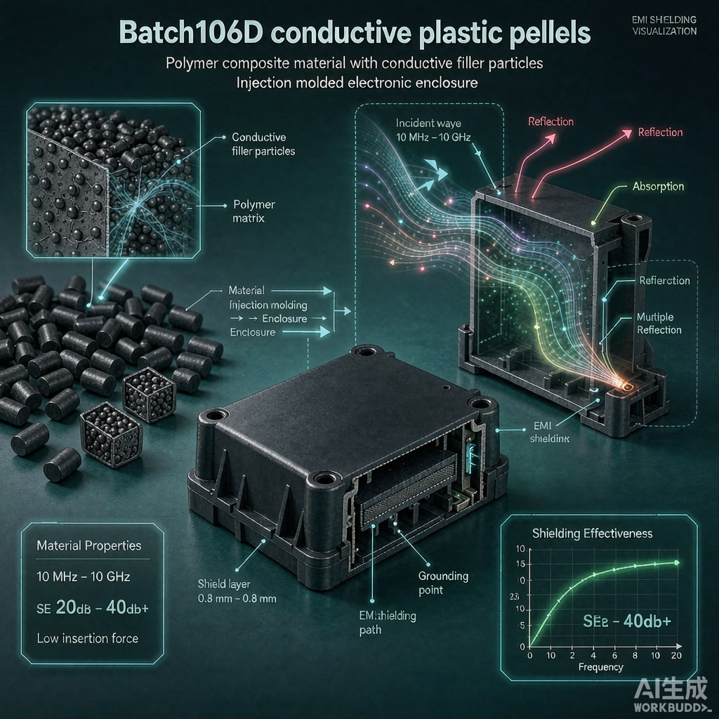
Metal EMI shields add weight, assembly steps, and galvanic corrosion risks in compact SMT devices. Conductive plastic pellets offer an alternative: injection-molded housings that provide both structural support and electromagnetic attenuation. These materials are widely used in automotive electronics, medical devices, telecom equipment, and handheld instruments where space and weight matter.
Common Conductive Fillers
The shielding performance of conductive plastics depends on the filler type, loading level, and dispersion. The most common options include:
- Nickel-coated graphite: Cost-effective, provides 40–60 dB shielding effectiveness at 30 MHz–1 GHz, and resists oxidation. Surface resistivity is typically 1–10 Ω/sq.
- Stainless steel fiber: Higher shielding, often 60–80 dB, and good mechanical strength. Fiber length and orientation strongly influence conductivity and flow marks.
- Carbon nanotubes (CNT): Enable lower loading for the same percolation threshold, preserving base resin properties. Best for applications needing transparency to visible light or very thin walls.
- Silver-coated particles: Highest conductivity and shielding but at a premium price, used in aerospace and military electronics.
Base Resin Selection
ABS, PC/ABS, PA66, PBT, and PP are common base resins for conductive pellets. ABS and PC/ABS offer good appearance and processability for consumer housings. PA66 and PBT are preferred for high-temperature automotive under-hood applications. PP is used when chemical resistance and low cost are priorities. The base resin must be dried properly before molding; moisture not only degrades mechanical properties but also creates voids that reduce conductive network continuity.
Molding Process Considerations
Conductive fillers are abrasive and increase tool wear, so molds should use hardened steel or coatings for long production runs. Injection speed and shear affect filler orientation and therefore shielding uniformity. Slower fill with balanced gates reduces flow-line weaknesses. High melt temperatures improve dispersion but can degrade some fillers; suppliers usually recommend a narrow processing window. Conductive pellets should be fed through dedicated equipment to prevent cross-contamination with standard resins.
Testing and Design Rules
Shielding effectiveness is typically measured with MIL-STD-285 or IEEE 299 methods, or by near-field sca
ing for board-level validation. Designers should provide a minimum wall thickness of 1.5–2.0 mm to ensure a continuous conductive path. Grounding features such as ribs, snaps, or metal inserts must make reliable electrical contact with the PCB ground plane. Joints between molded halves should use conductive gaskets or overlapping tongue-and-groove designs to prevent slot ante
a leakage.
Conclusion
Conductive plastic pellets merge EMI shielding with structural housing in a single molding step. Choosing the right filler and resin, controlling processing, and designing effective grounding features can match or exceed traditional metal-can shielding in many SMT applications.



