## Introduction
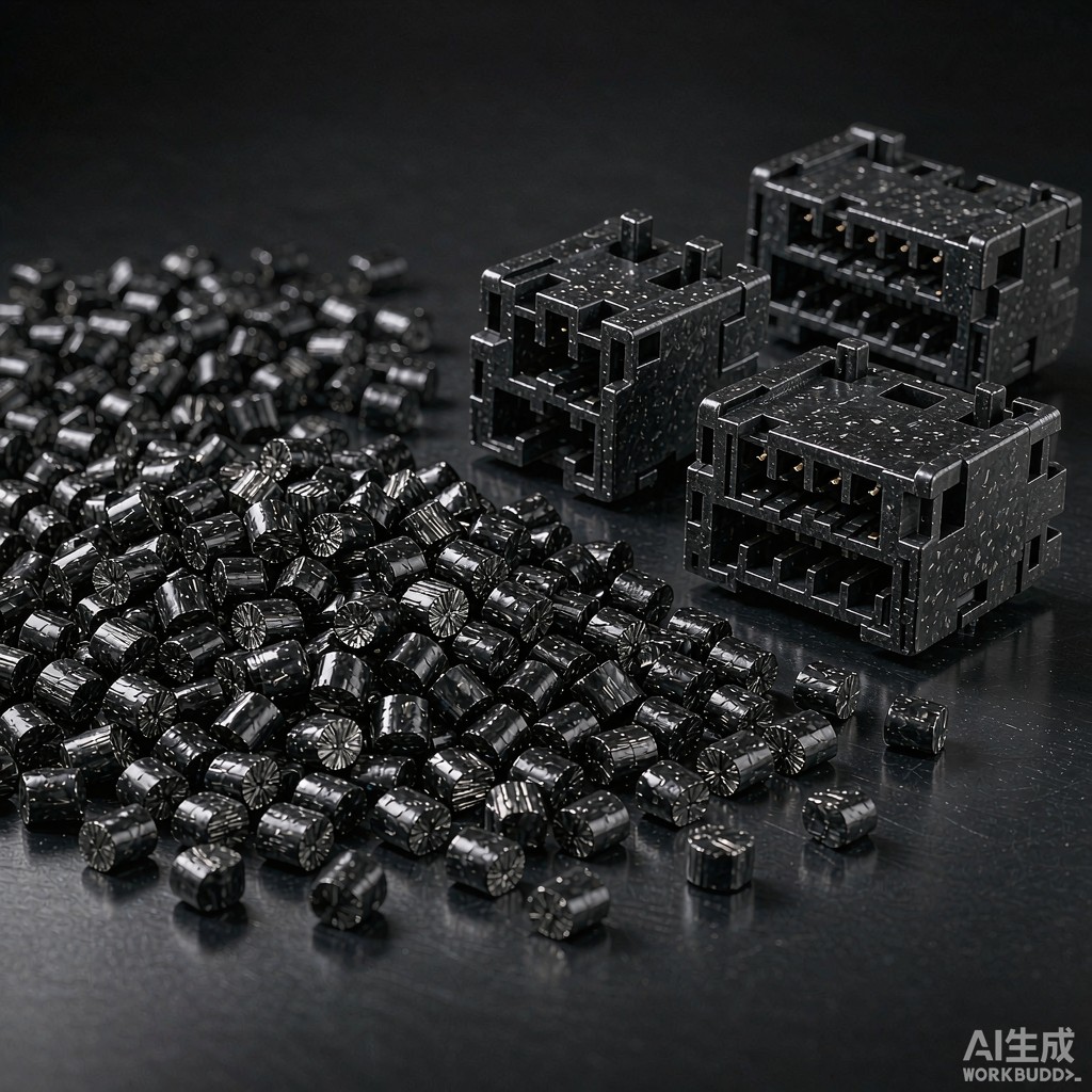
Polyphenylene sulfide (PPS) is a semi-crystalline engineering thermoplastic known for its exceptional thermal stability, chemical resistance, and dimensional stability. When reinforced with 30–40% carbon fiber, PPS modified plastic pellets produce injection-molded components that survive lead-free reflow soldering at peak temperatures of 260 degrees C while maintaining tight dimensional tolerances — a requirement increasingly demanded by automotive, aerospace, and 5G telecommunications SMT co
ector applications.
This article examines the properties, processing guidelines, and application performance of carbon fiber reinforced PPS (CF-PPS) modified plastic pellets, with specific focus on SMT co
ector housing requirements.
## Material Properties of CF-PPS Modified Pellets
### Thermal Properties
The thermal performance of CF-PPS is driven by PPS’s inherent high glass transition temperature (Tg approximately 90 C) and melting point (Tm approximately 280 C). The carbon fiber reinforcement further enhances thermal performance:
– Heat deflection temperature (HDT) at 1.82 MPa: 260–270 C — well above the 240–260 C peak reflow temperature, ensuring the housing maintains shape during soldering.
– Coefficient of thermal expansion (CTE): 9–15 ppm/C in the flow direction and 20–30 ppm/C in the cross-flow direction — closely matched to copper (17 ppm/C) and silicon (3-4 ppm/C), reducing thermal stress at interfaces.
– Thermal conductivity: 0.8–2.0 W/m-K (versus 0.25 W/m-K for unfilled PPS) — providing modest heat spreading capability for co
ector thermal management.
### Mechanical Properties
Carbon fiber at 30–40% loading dramatically improves mechanical performance:
– Tensile strength: 180–220 MPa (versus 75–85 MPa for unfilled PPS).
– Flexural modulus: 18–25 GPa (versus 4 GPa for unfilled).
– Izod notched impact: 8–12 kJ/m2 — lower than glass fiber reinforced PPS but adequate for co
ector housings.
– Compression strength: 220–280 MPa — critical for co
ector contact retention force under mating cycles.
### Electrical Properties
A notable feature of carbon fiber reinforced PPS is its electrical conductivity. Carbon fibers create a conductive network through the polymer matrix, providing:
– Surface resistivity: 10–100 ohm/square — sufficient for electrostatic discharge (ESD) protection without requiring conductive additives.
– Volume resistivity: 10–1000 ohm-cm.
– EMI shielding effectiveness: 40–60 dB at 1 GHz — providing inherent EMI shielding for the co
ector housing without requiring separate conductive coatings.
This ESD/EMI dual functionality eliminates the need for secondary shielding coatings, reducing manufacturing steps and cost for shielded co
ector applications.
### Chemical and Environmental Resistance
PPS is inherently resistant to a broad range of chemicals:
– Resists all common SMT cleaning solvents (isopropanol, terpenes, aqueous saponifiers).
– Resists automotive fluids (motor oil, transmission fluid, coolant, brake fluid).
– Low water absorption: 0.02–0.05% after 24-hour immersion (versus 0.5–2.0% for nylon) — critical for electrical property stability in humid tropical environments.
– Resists hydrolysis — no strength loss after 1000 hours at 85 C / 85% RH (IEC 60068-2-78).
## Processing Guidelines for Injection Molding
### Drying
PPS has very low moisture absorption and technically does not require pre-drying. However, surface condensation on cold pellets transferred to a warm hopper can cause splay marks. Best practice is to dry at 120–140 C for 2–3 hours or use a hopper dryer at 120 C.
### Melt Temperature
The recommended melt temperature range for CF-PPS is 300–340 C. Lower temperatures (300–320 C) produce better fiber preservation and mechanical properties; higher temperatures (320–340 C) improve flow for thin-wall co
ector housings but can degrade fibers and reduce mechanical performance.
### Mold Temperature
Mold temperature of 120–150 C is critical for achieving full crystallization. PPS crystallizes slowly at low mold temperatures, producing an amorphous part with poor mechanical and thermal properties. Mold temperatures below 100 C produce parts with HDT of only 120–150 C — inadequate for reflow survival.
### Injection Speed and Pressure
High injection speeds (100–200 mm/s) are recommended to prevent premature solidification in thin-wall co
ector features. However, high speeds can cause fiber attrition, reducing fiber length from an initial 3–6 mm to 0.1–0.4 mm in the molded part. The remaining fiber length determines mechanical performance — longer fibers provide higher strength and impact resistance.
### Screw Design and Wear Considerations
Carbon fiber is abrasive and will wear standard nitrided screws rapidly. Use a bimetallic barrel and screw (X-800 or similar) with a wear-resistant check ring. The L/D ratio should be 20:1 to 24:1 with a compression ratio of 2.5:1 to 3.0:1. Expect screw and barrel life of 50,000–100,000 cycles versus 300,000+ for glass fiber reinforced grades.
## Reflow Survival Performance
### Lead-Free Reflow Compatibility
The standard lead-free reflow profile (SAC305 solder) has a peak temperature of 240–250 C for 30–90 seconds, with total time above liquidus (TAL) of 60–90 seconds. The entire profile lasts 5–7 minutes.
CF-PPS co
ector housings survive this profile without warpage, blistering, or dimensional change. Key performance metrics:
– Post-reflow dimensional change: less than 0.05%.
– Post-reflow weight loss: less than 0.1% (indicating minimal outgassing).
– No blistering or surface defects.
– Contact retention force: within 5% of pre-reflow values.
For high-temperature lead-free profiles (SnCuNiGe solder, peak 260–270 C), CF-PPS survives with dimensional change under 0.1%, while glass fiber reinforced PPS may show 0.15–0.25% dimensional change due to higher CTE.
### Moisture Sensitivity
PPS is classified as MSL 1 (unlimited floor life at 30 C / 85% RH) per IPC/JEDEC J-STD-020. Unlike nylon or PBT, PPS does not absorb moisture that could cause popcorning during reflow. This eliminates the need for dry-bag packaging and allows open-floor handling in SMT assembly lines.
## Application Comparison: CF-PPS vs GF-PPS vs LCP
| Property | CF-PPS 40% | GF-PPS 40% | LCP 30% GF |
|—|—|—|—|
| HDT at 1.82 MPa | 265 C | 260 C | 240 C |
| Tensile strength | 200 MPa | 170 MPa | 160 MPa |
| CTE (flow direction) | 12 ppm/C | 20 ppm/C | 5 ppm/C |
| Surface resistivity | 10-100 ohm/sq | 10^14-10^16 ohm/sq | 10^14-10^16 ohm/sq |
| EMI shielding (1 GHz) | 40-60 dB | 0 dB | 0 dB |
| Wear on tooling | High | Low | Low |
| Cost per kg | $12-18 | $7-12 | $18-28 |
| MSL rating | 1 | 1 | 1 |
CF-PPS is the clear choice when ESD/EMI functionality is needed alongside thermal stability, despite higher cost and tooling wear. For purely structural applications without EMI requirements, GF-PPS offers comparable thermal performance at lower cost.
## Conclusion
Carbon fiber reinforced PPS modified plastic pellets provide a unique combination of properties for SMT co
ector housing applications: reflow survival at 260 C, inherent ESD protection and EMI shielding, chemical resistance, and dimensional stability in humid tropical environments. While the higher material cost and tooling wear compared to glass fiber reinforced grades must be factored into the total cost equation, the elimination of secondary EMI coating operations and the MSL 1 moisture classification often make CF-PPS the most cost-effective solution for demanding co
ector applications. For SMT manufacturers in Southeast Asia, where ambient humidity and temperature are high, the moisture immunity and thermal stability of CF-PPS are particularly valuable.



