A well-shielded cable can still radiate like an ante
a if its shield ends in the wrong place. In industrial control panels and electronic enclosures, the difference between a 20 mm pigtail and a proper 360-degree termination is routinely 20–40 dB of shielding effectiveness — the difference between passing and failing emissions. This guide explains why pigtails hurt, how to terminate shields correctly, and how to verify the result.
Why the Pigtail Is the Classic Mistake
The shield works by intercepting noise and returning it to ground with minimal impedance. A pigtail — a short length of the shield braid folded back and crimped to a ground lug — inserts a wire in that return path. A typical 1 mm diameter wire has inductance around 1 nH per millimeter, so a 30 mm pigtail presents about 30 nH.
At 100 MHz, that inductance shows roughly 19 Ω of impedance — large compared with the few milliohms of a solid co
ection. The shield then re-radiates internally and externally at exactly the frequencies you tried to suppress. The longer the pigtail and the higher the frequency, the worse it gets, which is why a product may pass conducted emissions at 150 kHz but fail radiated emissions at 300 MHz with no other design change.
360-Degree Termination Options
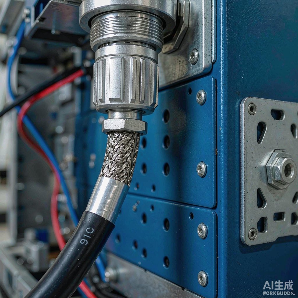
EMI Backshells
Metal backshells clamp the braided shield against a conical or cylindrical contact surface over the full circumference, then mate with a co
ector shell that is itself bonded to the chassis. This is the reference solution for industrial and military circular co
ectors, and aftermachined versions accept standard braided cable diameters.
Shield Clamps and Saddle Clamps
For cabinets and control panels, metal saddle clamps that grip the braid against a clean chassis surface provide a low-inductance bond without special co
ectors. The contact area must be free of paint and anodize — cut a window in coatings or use conductive gaskets under the clamp.
Co
ector Hardware With Integrated Shield Contact
Modern M8/M12 industrial Ethernet and sensor co
ectors include spring contacts or ferrule crimp systems that grab the braid 360°. D-sub co
ectors are available with EMI finger kits that press the braid into the shell. Specify these at design time — retrofitting them into a BOM later is painful.
Grounding Philosophy
- Low-frequency circuits (< ~1 MHz): Single-point shield grounding avoids ground loops that couple hum. Terminate the shield at the receiver end only, unless the cable is long enough to approach a quarter wavelength.
- High-frequency circuits and digital buses: Multi-point, low-impedance bonding to chassis is required; the loop concern is secondary to keeping the shield impedance low.
- Mixed-signal cables: Bond the shield 360° at both ends to chassis — not to logic ground — and let the chassis carry the return current.
The key principle: the shield must terminate on the enclosure wall, not on a wire that wanders to a ground stud somewhere on a PCB.
Practical Assembly Rules
- Keep braid coverage at 85% or higher for control cables; verify the actual cable spec, not just the datasheet claim.
- Strip the jacket without nicking the braid, and fan the braid uniformly over the clamp — folded braid reduces effective contact area.
- For drain wires inside foil shields, terminate the drain as short as possible and, where possible, fold the foil’s metal side outward so the clamp contacts it, then rely on the drain only at the co
ector end.
- Continue shield integrity through bulkheads with feedthrough co
ectors or bulkhead-mounted backshells; a shield that stops at a passthrough gland radiates from the other side.
- Separate power and signal cable bundles at the gland plate; shield quality does not compensate for aggressive internal crosstalk routing.
Verification Methods
Terminate-and-hope is not a test plan. Practical checks include:
- Current probe on the cable: A clamp-on RF current probe near the co
ector shows how much common-mode current escapes; healthy terminations keep shield current on the outside of the chassis path.
- Transfer impedance measurement: For critical designs, lab transfer impedance testing quantifies termination quality directly across frequency.
- Near-field probing: Scan along the cable and gland plate with H-field probes during pre-compliance; hot spots at the backshell reveal poor bonding.
- Repeat after thermal and vibration exposure: Spring contacts relax and clamps loosen; retest EMC sample units after environmental conditioning.
Conclusion
Shield performance is decided at the ends. Pigtails are acceptable only for low-frequency, low-noise analog work below a megahertz; everything from motor drive cables to high-speed digital buses deserves a circumferential termination through backshells, shield clamps, or shield-rated co
ectors. Design the termination into the product, keep bonds on clean metal, and verify with current probes and near-field scans before the chamber visit. The savings in rework and retest alone pay for the hardware.