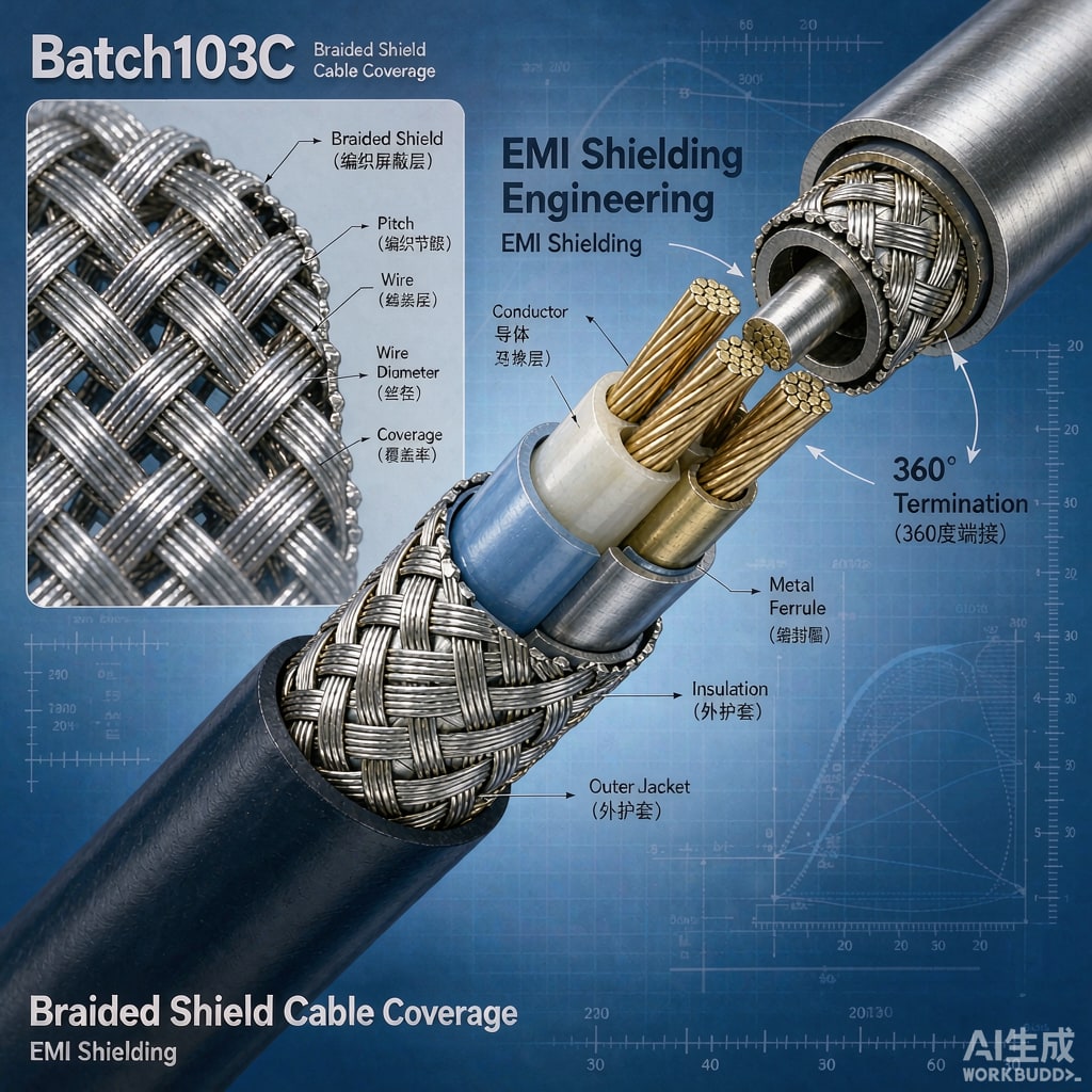
Cable assemblies are often the weakest link in an otherwise well-shielded system. Radiated emissions escaping through or coupling onto external cabling account for a large share of failed CISPR and FCC pre-scan results. When the fix involves braided shields, two specifications govern the outcome: optical coverage and transfer impedance. Understanding both lets engineers order cable that actually solves the problem instead of merely looking shielded.
Optical Coverage: What the Percentage Really Means
Optical coverage describes the fraction of the cable surface physically covered by braid wires when viewed as a projected surface. A 95 percent coverage braid leaves small diamond-shaped gaps between wire crossings; at 85 percent those gaps widen considerably. Coverage follows from carrier count, wires per carrier, picks per inch, and wire diameter, and it can be calculated precisely for any braid pattern.
However, coverage alone is a poor predictor of high-frequency performance. At low frequencies, shielding effectiveness tracks coverage fairly well. Above roughly 10 to 30 MHz, the braid’s own construction quality—wire-to-wire contact resistance at crossings—begins to dominate, and that is captured by a different metric entirely.
Transfer Impedance: The Honest Metric
Transfer impedance ZT is defined as the voltage induced per unit length on the inside of the shield by current flowing on the outside. Lower is better; a shield with 1 mΩ/m transfer impedance couples almost nothing, while 100 mΩ/m can leak enough to fail radiated emissions.
ZT behavior with frequency has three regions:
- DC to ~1 MHz: ZT equals the DC resistance of the braid and falls as frequency rises (skin effect pushes current to the outer surface).
- Mid-band (~1–100 MHz): the plateau region, dominated by the braid weave. Single braids of ti
ed copper typically plateau at 5 to 30 mΩ/m depending on coverage and weave tightness. Poor weave contact raises this plateau and lets emissions escape.
- High frequency (>100 MHz): apertures and spiral leakage between braid wires cause ZT to rise again. This is where double braids and foil combinations earn their keep.
Single Braid, Double Braid, or Foil Plus Braid?
Single 85 to 95 percent coverage ti
ed copper braid handles most industrial cables up to a few hundred MHz. Double braids (a braid over a braid, often with opposite lay directions) lower the mid-band plateau by 15 to 20 dB and delay the high-frequency rise, which suits test instruments and aerospace harnesses. Aluminum foil with drain wire plus an 80 percent braid—the common “foil-braid” construction in consumer and USB-type cables—achieves high optical coverage cheaply, and the foil seals the apertures that the braid leaves open, but foil shields rely on the drain wire for termination quality and lose effectiveness above several hundred MHz if terminated poorly.
Termination Dominates the Result
A superb braid terminated with a 30 mm pigtail to a ground point behaves, above 30 MHz, like almost no shield at all: the pigtail inductance (roughly 1 nH per mm) converts common-mode shield current into a radiating ante
a. Best practice is a 360-degree termination where the braid is compressed directly against the co
ector shell with a ferrule or clamp. When reviewing cable drawings, check the termination method before admiring the coverage percentage—most field EMI failures traced to cables are termination failures, not braid failures.
Writing the Specification
An effective procurement spec for a shielded cable includes:
- Braid material (ti
ed or bare copper, or silver-plated for high frequency), wire diameter, and construction: carriers × wires per carrier, picks per inch
- Optical coverage, typically 90 to 95 percent minimum for general use
- Transfer impedance limit at defined frequencies, e.g. ZT ≤ 10 mΩ/m at 10 MHz and ≤ 50 mΩ/m at 100 MHz, measured per IEC 62153-4-3
- Termination method: 360-degree ferrule with specified contact pressure, or a defined maximum pigtail length with justification
- Continuity and shielding effectiveness acceptance test at production, such as a surface transfer impedance sample test per lot
Conclusion
Optical coverage tells you how much metal is on the cable; transfer impedance tells you how well it works. Specify both, and pay equal attention to the shield termination, because a perfect braid behind a poor pigtail delivers none of its rated performance. Engineers who adopt ZT-based specifications consistently see fewer radiated emissions surprises during compliance testing and fewer noise complaints in the field.



